
Leg attachment and method for manufacturing same

Inactive Publication Date: 2005-08-09
JSJ FURNITURE CORP
View PDF13 Cites 14 Cited by
  • Summary
  • Abstract
  • Description
  • Claims
  • Application Information

AI Technical Summary

Benefits of technology

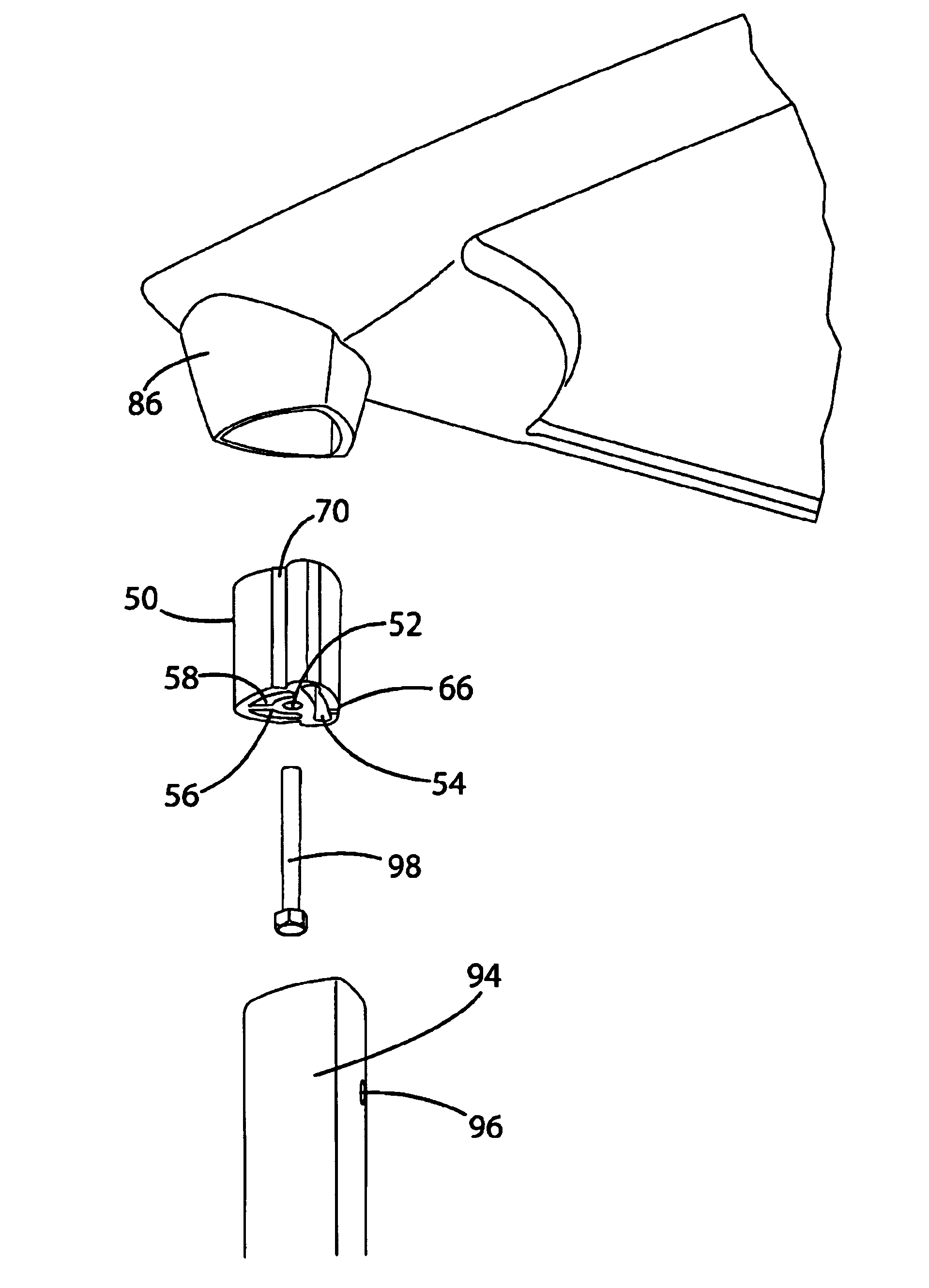
[0009]The present invention provides several advantages over prior leg attachment mechanisms. First, the leg is easily attached to the article of furniture because a minimum number of parts are involved. In the preferred embodiment, only a single set screw is tightened to attached each leg. Also, it is difficult to incorrectly install the leg. In a preferred embodiment, the leg defines an opening permitting access to the set screw. The set screw will be accessible only when the leg is properly installed. Second, the connection between the leg and the post is highly secure. Because the post is wedge shaped, there is a high degree of engagement between the post and the inner surfaces of the leg. As the post expands, all three walls of the post are driven more forcefully against the corresponding surfaces of the leg. Third, because the bracket and post are separate pieces, the bracket can be secured to the article of furniture by a fastener located immediately beneath the leg. This reduces any “fulcrum” effect that might be caused by an offset fastener. Fourth, the use of a separate post permits the bracketed to be overmolded before the post is attached. This eliminates the concern that the mold will be damaged by the post. Further, the flexible plug permits an undercut void to be formed to receive the leg. This eliminates the need for a conventional draft angle in the mold and ultimately provides a tighter fit of the overmold around the leg. Fifth, the assembly is aesthetically pleasing because the leg attachment mechanism is hidden beneath foam.

Problems solved by technology

Several problems result from this type of leg attachment.
One problem is that it can be complicated to assemble the legs to the furniture.
It is often difficult for an end consumer to figure out where each part needs to be connected, and there is a danger of losing some of the parts, especially smaller parts like screws.
Another problem is the ability of the furniture to withstand force.
If the bracket and screw assembly is not robust enough or the legs are not properly attached to the furniture, the furniture may buckle or collapse under heavier loads.
Yet another problem with bracket and screw assemblies is that they are aesthetically unpleasing.

Method used


Image

  • Leg attachment and method for manufacturing same
  • Leg attachment and method for manufacturing same
  • Leg attachment and method for manufacturing same

Examples


Embodiment Construction

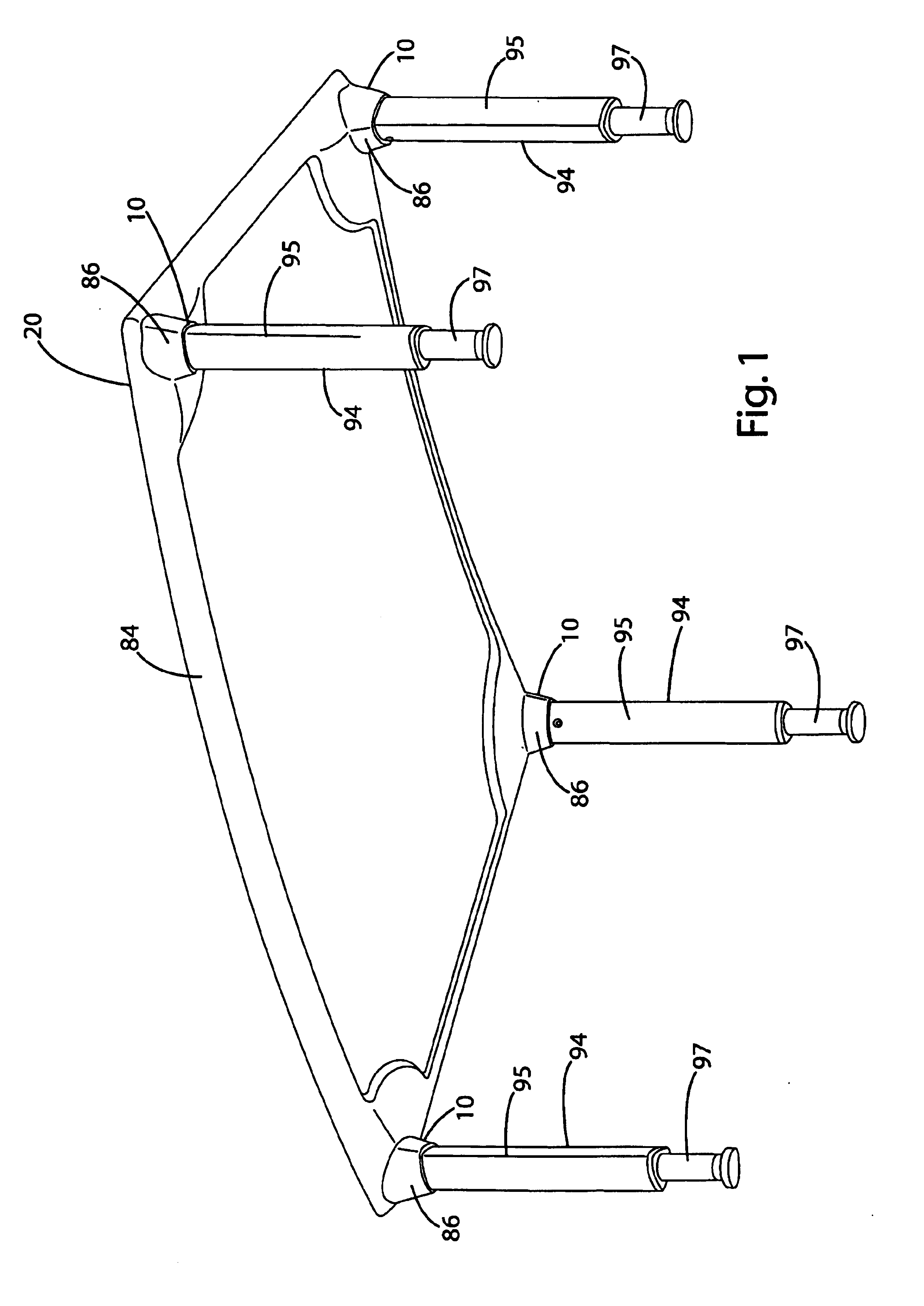
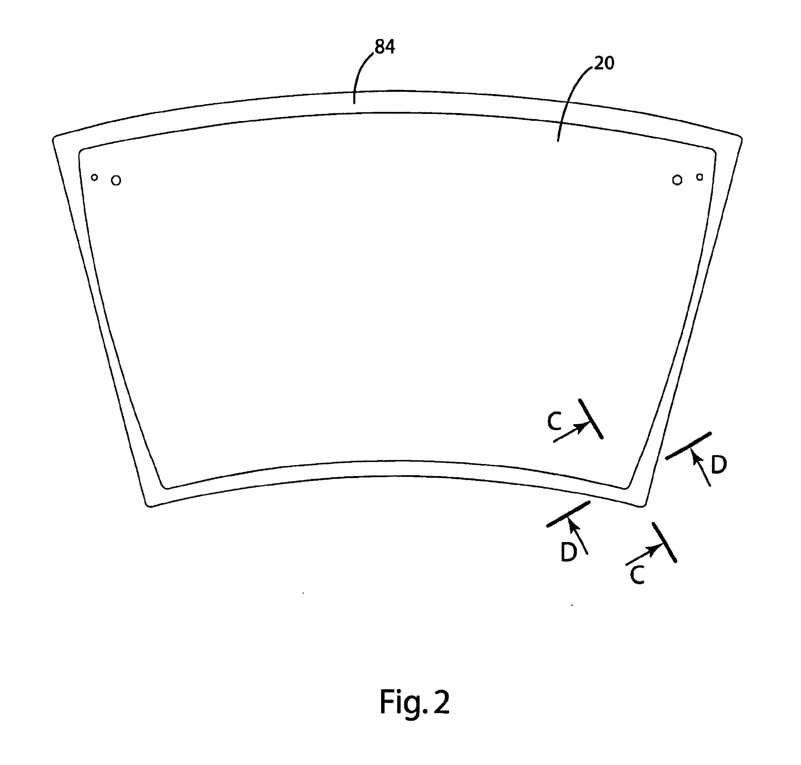
[0021]A table 20 incorporating a leg attachment mechanism 10 in accordance with a preferred embodiment of the present invention is shown in FIG. 1. The leg attachment mechanism 10 is intended to be used with an article of furniture to allow for the easy attachment of legs to the article of furniture. FIG. 1 shows the leg attachment mechanism 10 connected to a table 20, with one leg attachment mechanism 10 located in each corner of the table 20. The leg attachment mechanism 10 is, however, well suited for use in attaching legs to a wide variety of articles of furniture. As shown in FIGS. 2-4, the leg attachment mechanism 10 generally includes a bracket 30, screws 44 for attaching the bracket 30 to the table 20, a post 50, and a bolt 98 for attaching the post to the bracket. The leg attachment mechanism 10 may optionally have foam 84 surrounding part of the table 20, the bracket 30, and part of the post 50. In use, the post 50 is fitted within the leg 94 and expanded by set screw 80 t...


PUM


Abstract

A leg attachment mechanism and a method of manufacture for an article of furniture including a bracket attached to the article of furniture and an expandable post attached to the bracket. The leg includes a receptacle of sufficient dimension to receive the post. The leg is attached to the post by fitting the receptacle over the post and then expanding the post to forcefully engage the walls of the leg defining the receptacle. The post preferably includes a flexible wall that is movable outwardly by rotation of a threaded element, such as a set screw. A foam overmold is preferably formed over the edge of the article of furniture and the bracket. The overmold preferably includes an undercut boot that closely receives upper end of the leg.

Description

BACKGROUND OF THE INVENTION[0001]The present invention relates to furniture and, more specifically, to furniture leg attachment mechanisms and related components.[0002]Many pieces of furniture have rigidly attached legs. Pieces of furniture with long legs, such as tables, are often delivered to the end consumer without the legs attached. The furniture takes up less space and is easier to transport without the legs already attached. The furniture suppler or the end consumer must then attach the legs to the furniture.[0003]Typically legs are attached to furniture using brackets and screws. Several problems result from this type of leg attachment. One problem is that it can be complicated to assemble the legs to the furniture. With bracket and screw assemblies, it is necessary to work with several small parts. It is often difficult for an end consumer to figure out where each part needs to be connected, and there is a danger of losing some of the parts, especially smaller parts like sc...

Claims


Application Information

Patent Timeline
IPC IPC(8): A47B13/00A47B13/02
CPCA47B13/021
Inventor BABICK, TOD G.HOFFMAN, DENIS H.BENEFIEL, ROBERT A.
Owner JSJ FURNITURE CORP
Learn More