Counter-rotating twin shaft system for gardening machines

a technology of counter-rotating and gardening machines, which is applied in the field of counter-rotating twin shaft systems for gardening machines, can solve the problems of uneven tilling of the ground and/or tilling to a very shallow depth, and neither the drag bar system nor the counter-rotating wheel alone produce any useful work

Inactive Publication Date: 2005-08-09
LEE KAI S
View PDF9 Cites 17 Cited by
  • Summary
  • Abstract
  • Description
  • Claims
  • Application Information

AI Technical Summary

Benefits of technology

[0016]In addition, embodiments of the gardening / landscaping system include alternative orientations of the associated shafts and related ground manipulation tools and cutters, thereby enabling the gardening / landscaping system to accomplish a variety of tasks including but not limited to, tilling, edging, trenching, root cutting, brush cutting, tree and tree stump cutting, lawn mowing and snow removal.

Problems solved by technology

While conventional rotor tillers utilizing a single shaft may do an adequate job of tilling previously tilled soils or light soils, conventional tillers do not perform as well in hard soils, soils containing rocks and other debris, and / or soils containing a significant amount of root systems therein.
Additionally, the conventional tiller will typically “walk” over these hard soils and skip areas, resulting in uneven tilling of the ground and / or tilling to a very shallow depth.
However, neither the drag bar system nor the counter-rotating wheel by itself produces any useful work other than holding the machine back from advancing too quickly across the ground.
Yet another problem is that the motion of the tines often overpowers the stopping force of the drag bar or the traction of the counter-rotating wheels, thus resulting in an uncontrollable back-and-forth jerking motion of the tiller and an uneven tilling of the soil.
As a result, the operator must pull and shove the machine forward and backward in order to smooth the advance of the machine in hard or debris-filled soils, thereby causing fatigue of the operator.
A problem associated with most rototillers that include rearwardly located tines is that these machines are large, heavy, are difficult to turn, and require the operation of numerous controls to maneuver.
Yet another problem with conventional rototillers is that hard soils dislodged by conventional rototillers typically remain in large chunks often requiring further breaking apart, either manually or by repeated passes with the tiller.
Still yet another problem with conventional rototillers is that these tillers may not be able to remove foreign materials from within the soil, such as large or heavy root systems.
Therefore, attempting to place a garden plot near a heavily wooded area may be impossible, or may require manually digging up and severing the root system independent of the tilling operation.
Finally, conventional tillers are not capable of removing brush and / or small trees from a garden plot.
Besides the problems mentioned above, typically all conventional rototillers are designed for a single purpose, namely tilling or working the ground.

Method used


Image

  • Counter-rotating twin shaft system for gardening machines
  • Counter-rotating twin shaft system for gardening machines
  • Counter-rotating twin shaft system for gardening machines

Examples


Embodiment Construction

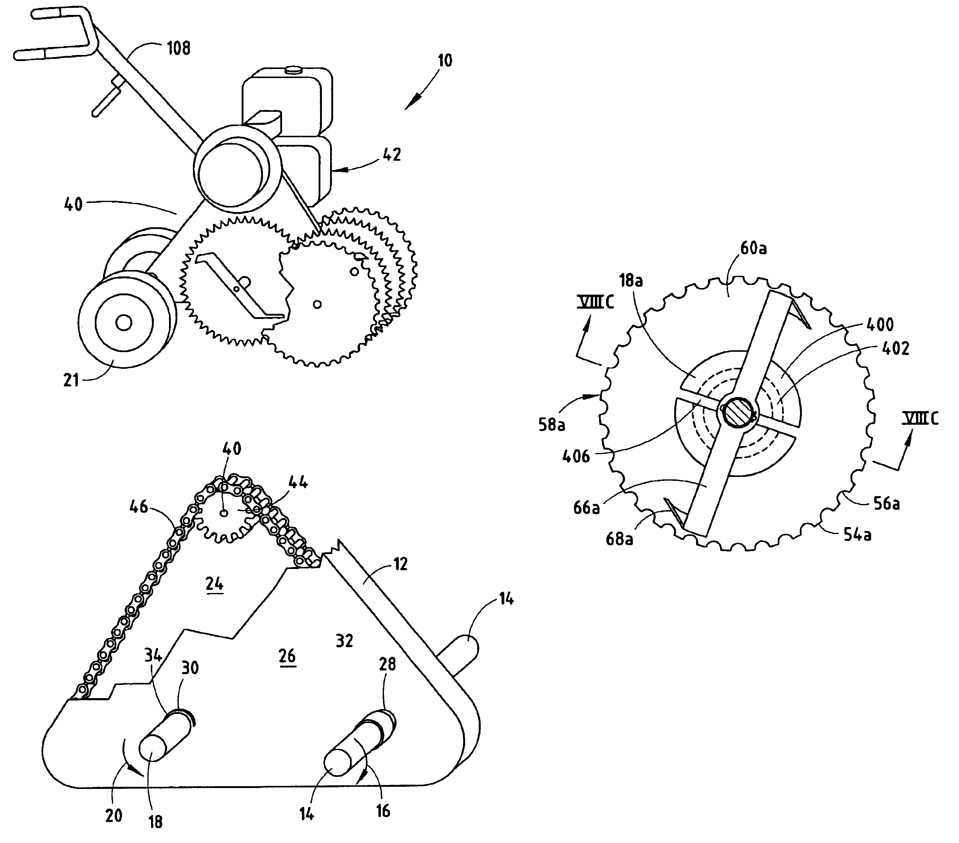
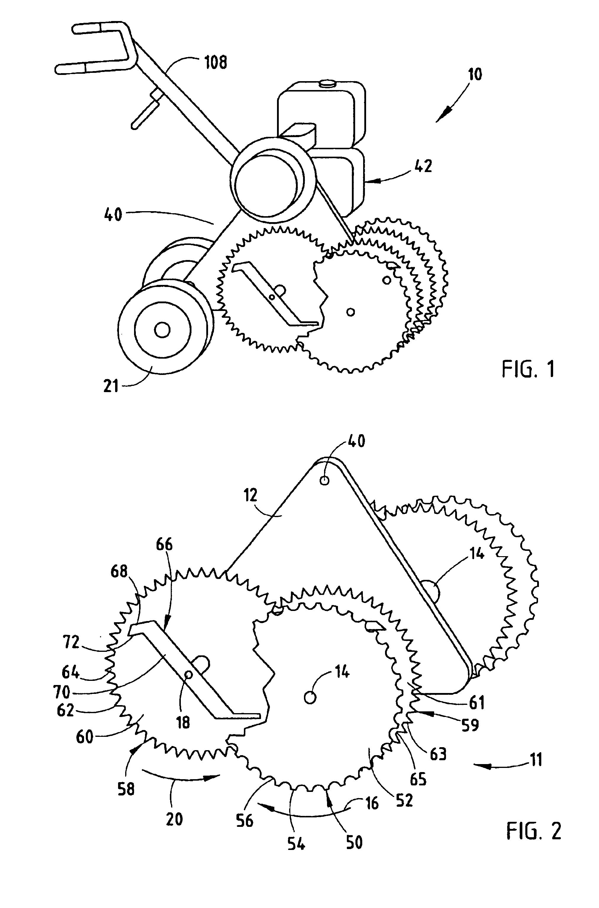
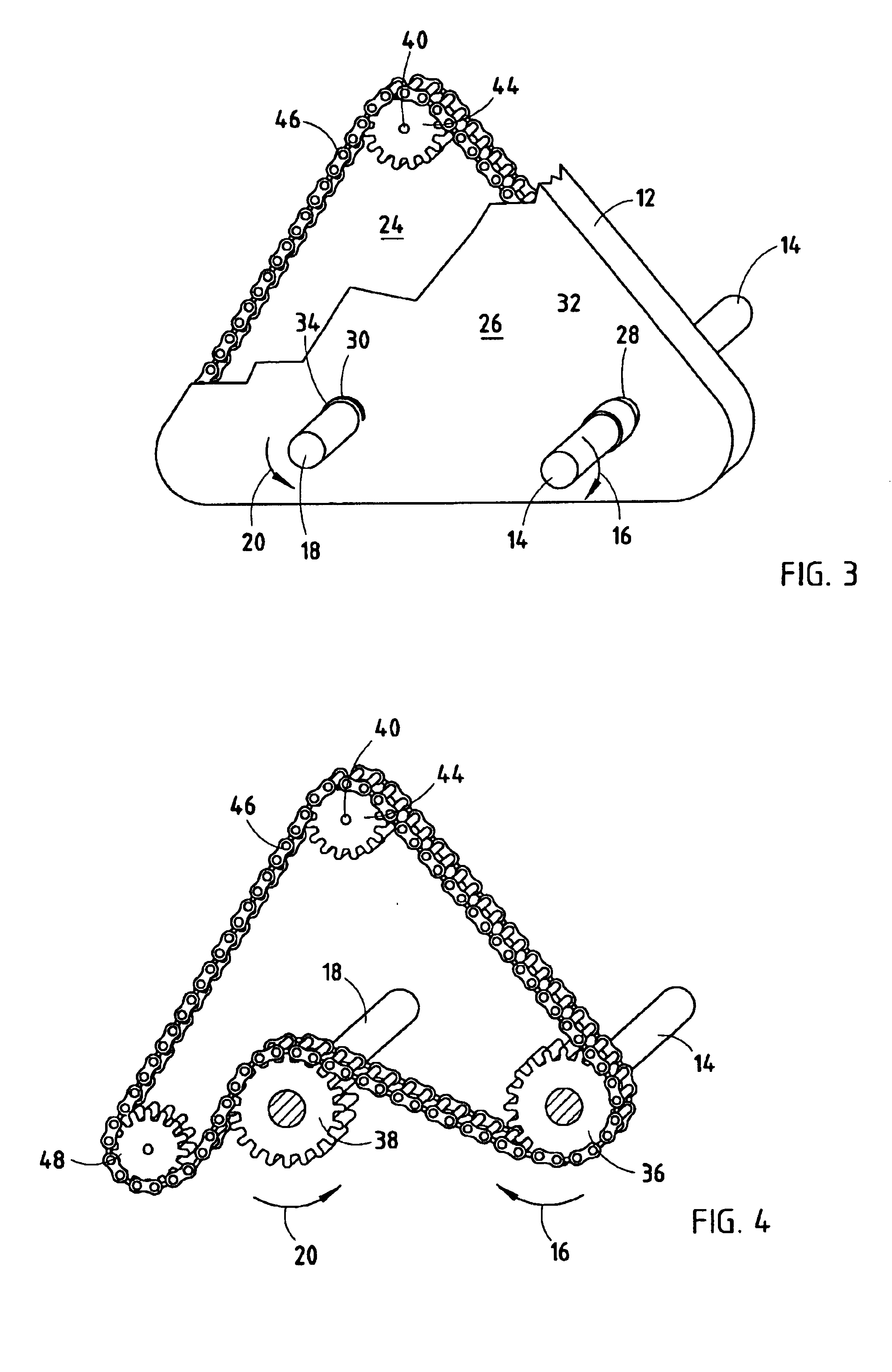
[0049]For purposes of description herein, the terms “upper,”“lower,”“right,”“left,”“rear,”“front,”“vertical,”“horizontal,” and derivatives thereof shall relate to the invention as oriented in FIG. 1. However, it is to be understood that the invention may assume various alternative orientations and step sequences, except where expressly specified to the contrary. It is also to be understood that the specific devices and processes illustrated in the attached drawings and described in the following specification are exemplary embodiments of the inventive concepts defined in the appended claims. Hence, specific dimensions and other physical characteristics relating to the embodiments disclosed herein are not to be considered as limiting, unless the claims expressly state otherwise.

[0050]The reference numeral 10 (FIG. 1) generally designates a gardening / landscaping system embodying the present invention. In the illustrated example, gardening / landscaping system 10 includes a working assem...


PUM


Abstract

A gardening / landscaping utility machine having a counter-rotating twin shaft system that can perform multiple types of work required for gardening / landscaping, including tilling, trench-edging, weeding, brush cutting, snow removal and lawn mowing. These processes can be accomplished by exchanging attachments from, or altering the orientation of, the counter-rotating twin shafts.

Description

BACKGROUND OF THE INVENTION[0001]The subject invention is directed toward a garden / landscaping utility system that includes a counter-rotating twin shaft system. This design eliminates many problems associated with conventional unidirectional-rotating single shaft systems and increases the utility of the subject garden / landscaping utility system.[0002]Conventional rototillers used for tilling soil and cultivating in gardening or agricultural work characteristically have a single shaft with a plurality of tines, usually four, affixed thereto. The shafts can be employed at either the front or rear of the associated tiller. With respect to rototillers employing a forwardly located shafts, an engine drives the shaft and the associated tines to rotate in unison in a single direction that simultaneously tills or works the ground and propels the rotor tiller in a forward direction or rearward direction. Rototillers employing a rearwardly located shafts typically also may rotate the shaft i...

Claims


Application Information

Patent Timeline
Patent Type & Authority Patents(United States)
IPC IPC(8): A01B33/02A01B33/00A01B33/08E01H5/04
CPCA01B33/028A01B33/082E01H5/04
Inventor LEE, KAI S.
Owner LEE KAI S
Why Eureka
Try Eureka