Sealing arrangements

Active Publication Date: 2005-08-09
ANSALDO ENERGIA SWITZERLAND AG
View PDF14 Cites 34 Cited by
  • Summary
  • Abstract
  • Description
  • Claims
  • Application Information

AI Technical Summary

Benefits of technology

[0012]Each sealing element is thus interposed between the seal plate and one of the machine elements and can protect the machine element against wear caused by movement of the seal plate. One or both sealing elements may be formed of a sufficiently soft material that it will not itself cause wear where it contacts the machine element and it can be resilient enough to accommodate the relative movement between the seal plate and the machine element. The sealing element is of relatively low cost and is expected to be replaced when the apparatus of which it forms part is serviced. It might therefore be described as a sacrificial sealing element.
[0013]As mentioned, at least one of the first and second sealing elements is advantageously formed of a resilient material and the neck portion of the channel shape is preferably sized to grip the seal plate. The channel shape of at least one of the first and second sealing elements may be convergent from the closed end to the neck and divergent from the neck to the open end. Complementary to the divergent shape of the at least

Problems solved by technology

A problem with this known sealing arrangement is that the relative movement between the seal plate and the housings causes wear on the seal plate and in the recesses, which leads to a degraded sealing function.
The seal plate can be replaced relat

Method used


Image

  • Sealing arrangements
  • Sealing arrangements
  • Sealing arrangements

Examples


Example

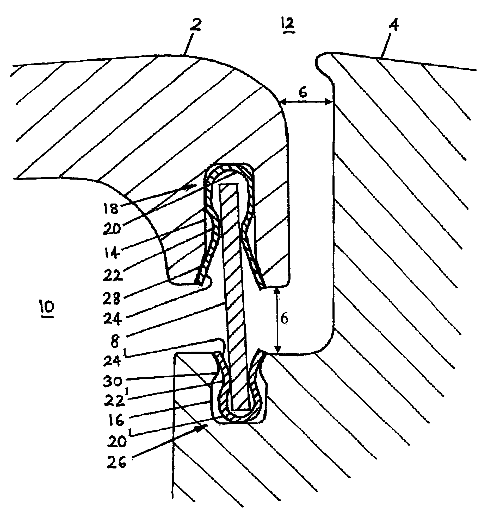
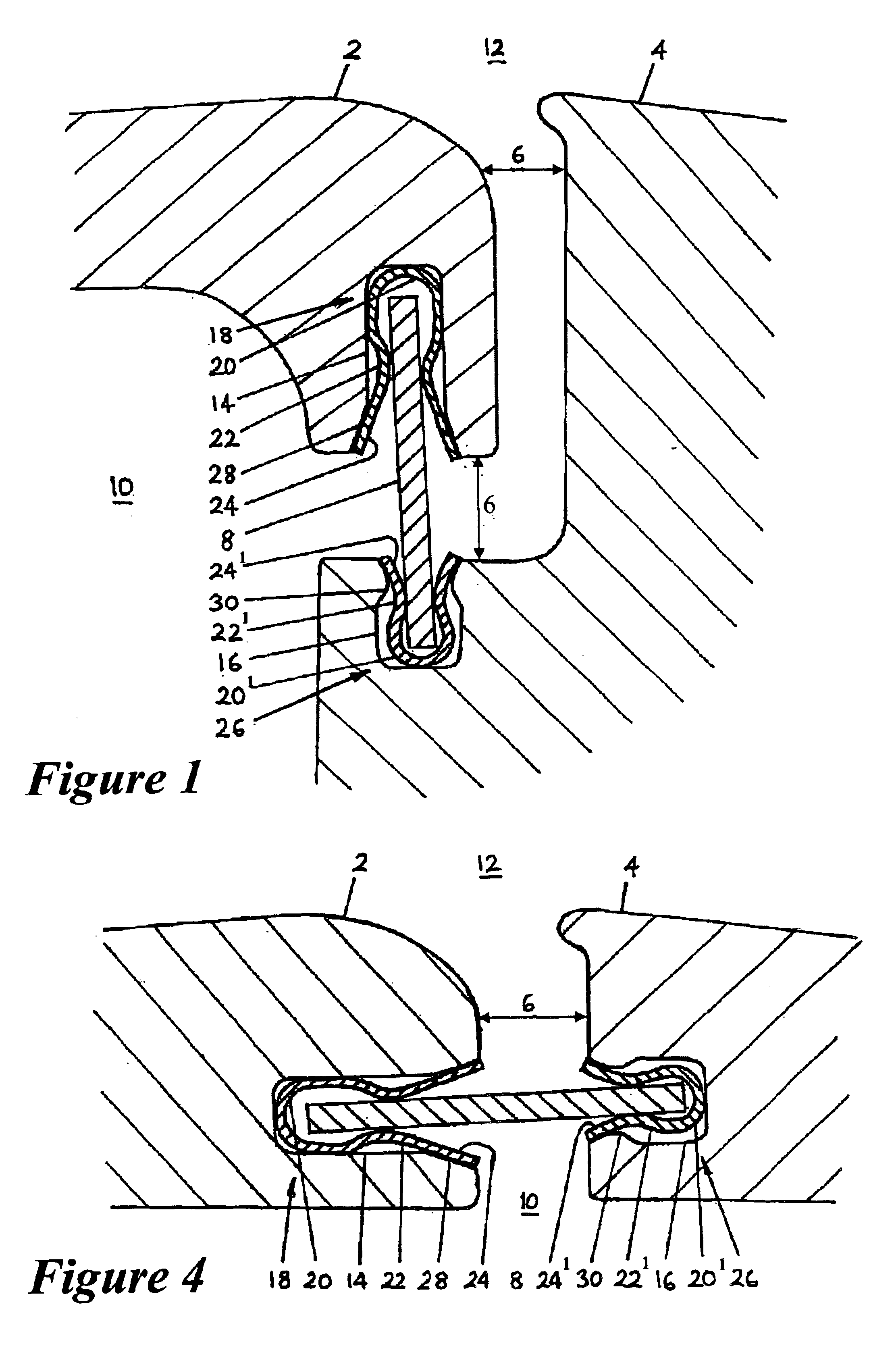
[0036]FIG. 1 illustrates in cross section the junction or joint between a first part 2 and a second part 4 of a housing of a gas turbine. The housing is generally cylindrical about an axis of the turbine (not shown) running horizontally below the lower edge of FIG. 1. A narrow gap 6 between the first and second parts of the housing 2,4 is bridged by a seal plate 8 to separate the interior 10 of the housing from the exterior 12. The seal plate 8 is a flat ring concentric with the axis of the housing and must be sufficiently rigid to withstand the pressure difference between the housing's interior 10 and its exterior 12 without excessive deformation. The outer edge of the seal plate 8 is received in an inwardly facing annular recess 14 of the first part 2 of the housing. An outwardly facing recess 16 in the second part 4 of the housing confronts the recess 14 across the gap 6 and receives the inner edge of the seal plate 8.

[0037]Located in the first annular recess 14 and interposed be...


PUM


Abstract

Sealing elements locate an annular seal plate in an annular recess. The sealing elements are each in the form of a ring or a segment of a ring comprising a channel-shaped cross-section, the mouth of which receives the seal plate. Each sealing element is thus interposed between the seal plate and a corresponding part of a machine element such as a turbine casing in which the recesses are provided. The sealing elements protect the casing against wear caused by movement of the seal plate relative to the casing. The sealing element is of relatively low cost and is expected to be replaced when the apparatus of which it forms part is serviced.

Description

TECHNICAL FIELD[0001]The invention relates to arrangements for fluid pressure sealing between adjacent machine elements such as two parts of a pressurized housing, in particular the casing of a turbomachine.BACKGROUND OF THE INVENTION[0002]Gas turbines and their associated compressors are operated at high temperatures and pressures and it is necessary for reasons of safety and efficiency that their housings or casings should securely contain the pressurized gases within. The housings are manufactured in several parts so an effective seal is required at the joints or junctions between those parts. Such seals must function under extreme conditions, particularly in the case of turbine housings, and must be able to accommodate relative movement between the housing parts caused by vibration and by differential thermal expansion during operation of the turbomachine.[0003]In an existing sealing arrangement between two adjacent parts of a generally cylindrical turbine housing, one part of t...

Claims


Application Information

Patent Timeline
IPC IPC(8): F01D11/00F01D25/24F16J15/08
CPCF01D11/005F01D25/24F16J15/0887F05D2240/57
Inventor HIRST, ROBERT
Owner ANSALDO ENERGIA SWITZERLAND AG
Why Eureka
Try Eureka