Method and device for forming an image

a technology of image sensor and image sensor, applied in the field of methods and devices for forming images, can solve the problems of limited dynamic range, method exhibit undesirable temporal aliasing, and complex and cost-intensive systems, and achieve the effect of significantly increasing the dynamic range of image sensors

Inactive Publication Date: 2005-08-09
CSEM CENT SUISSE DELECTRONIQUE & DE MICROTECHNIQUE SA RECH & DEV
View PDF15 Cites 31 Cited by
  • Summary
  • Abstract
  • Description
  • Claims
  • Application Information

AI Technical Summary

Benefits of technology

[0016]In the method according to the invention, the timing used to reset and interrogate the sequence of pixels in an image sensor is important. The ratio t=Tlong / Tshort is chosen to increase significantly the dynamic range of the image sensor, insuring, however, an overlap between the images. For example, the dynamic range of an image sensor can be increased by the method according to the invention from 70 dB to 110 dB using a ratio of t=100. During the long integration time, many pixels or rows of pixels can be interrogated and reset a first time, exposed during a second (much shorter) time interval, interrogated and reset a second time. Preferably, these operations are performed on all other pixels or rows of pixels during the long integration time of one pixel or row of pixels, so that the ratio t=Tlong / Tshort is equal to the total number of pixels or rows of pixels of the image sensor. Compared with the state of the art, this has three advantages. Firstly, at most two rows of pixel data have to be stored at one time, and it is completely unnecessary to acquire and store complete images before processing and merging the data. Secondly, the short exposure time occurs immediately after the long one, effectively assuring a quasi-instantaneous exposure. Thirdly, the same pixel location is employed to acquire image data for the different exposure times and no spatial aliasing can occur.

Problems solved by technology

Due to the limited storage capacity of these storage devices, the ratio of maximum storable photocharge to photocharge detection noise, called dynamic range, is also limited.
Unfortunately, natural scenes (where there is no control of lighting conditions) and indoor scenes with highly varying illumination have a dynamic range of between 100'000:1 and 1'000'000:1.
This results in a complex and cost-intensive system.
Consequently, such methods exhibit undesirable temporal aliasing.
This implies spatial undersampling and aliasing, which is particularly undesirable in the case of so-called highlights, i.e., localized very bright pixel values usually caused by specular reflections at objects in the scene.
This is particularly disturbing if the resulting images are processed further, leading to false contours and erroneous contrast values.

Method used


Image

  • Method and device for forming an image
  • Method and device for forming an image
  • Method and device for forming an image

Examples


Embodiment Construction

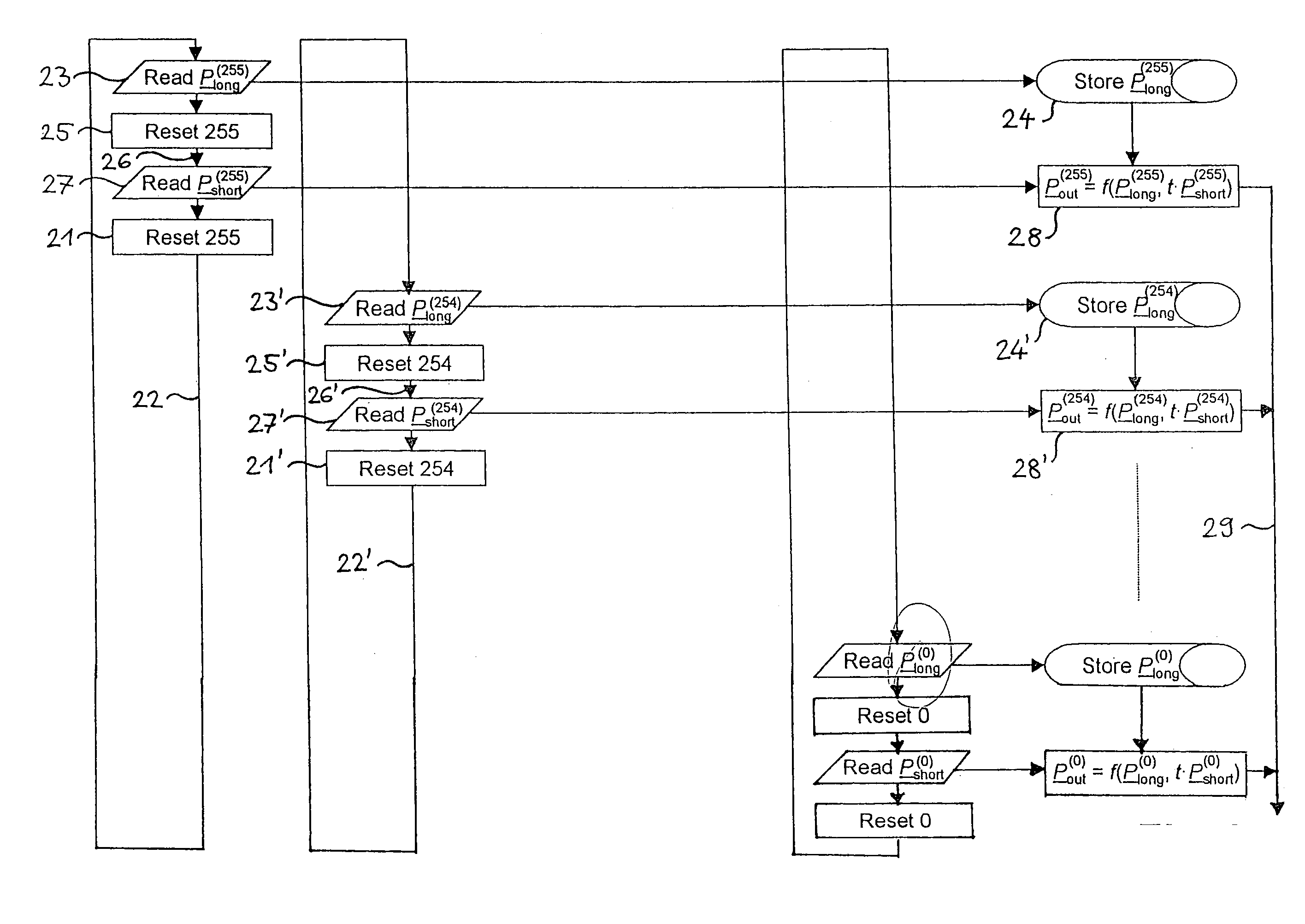
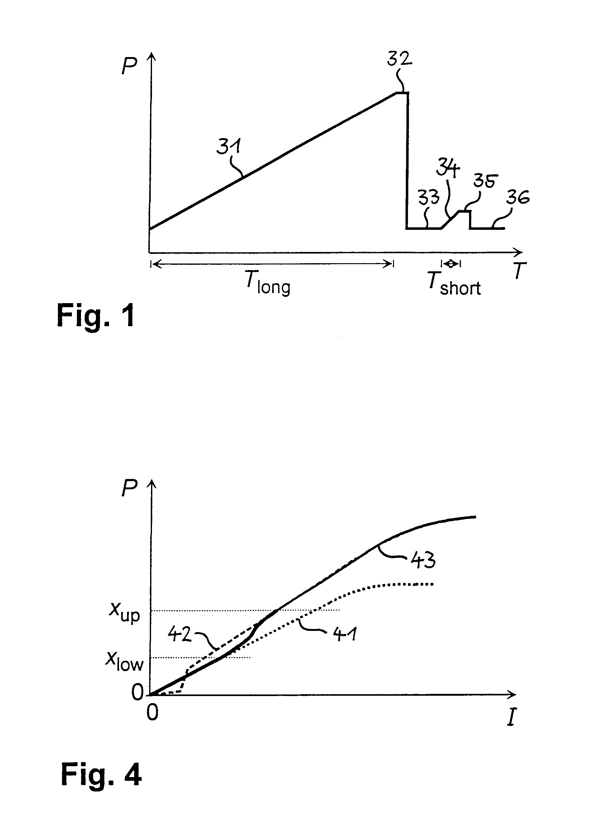
[0039]FIG. 1 schematically shows the output P of one given pixel as a function of time T in the method according to the invention. The figure illustrates an example in which two exposures, a first exposure 31 with a long exposure time Tlong and a second exposure 34 with a short exposure time Tshort, are performed on each subset of pixels. After the first exposure 31, the pixel output value is read out 32 and reset 33 for a first time. A second read-out 35 and, optionally, a second reset 36 are performed after the second exposure 34. Then, the pixel is ready for a further interrogation cycle. Of course, other variants of the method are possible in which, e.g., the first exposure time is shorter and the second one is longer, or in which more than two exposures are performed in one interrogation cycle.

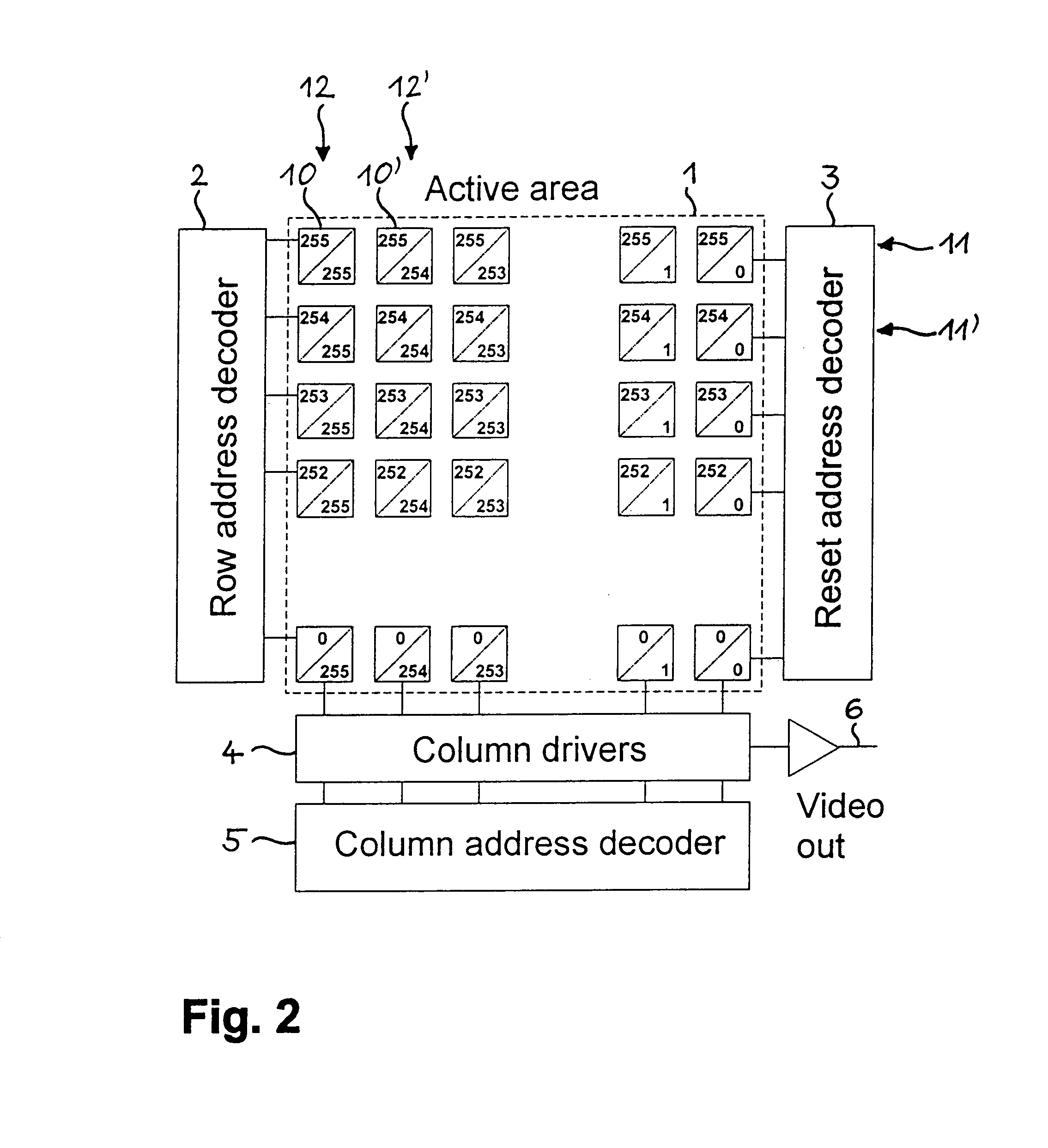
[0040]FIG. 2 shows a schematic of the architecture of an image sensor suited for carrying out the method according to the invention. In this exemplified embodiment, the image sensor has a...


PUM


Abstract

The method for forming an image with a wide dynamic range makes use of an image sensor containing subsets of pixels that can be individually reset. After an initial reset (21), a pixel or row of pixels is exposed (22) for a first time interval and the gray value(s) (Plong(255)) are read out (23) and stored (24). The pixel or row of pixels is then reset (25) and exposed (26) for a second, shorter time interval. The second gray value(s) (Pshort(255)) is/are read out (27) and either stored or immediately combined (28) with the first gray value(s) (Plong(255)) by means of a merging function (ƒ). The merging function (ƒ) ensures a monotonic, smooth change in output from the lowest to the highest gray values. The procedure is repeated for all pixels or rows of pixels in the image sensor, thus obviating the need for the storage of complete images. The method reduces temporal aliasing to a minimum and eliminates spatial aliasing.

Description

[0001]The invention relates to a method for forming an image and to an image sensor with an active area containing a plurality of pixels. It makes possible a wide dynamic range but obviates the need for a storage of complete images. It reduces temporal aliasing to a minimum and eliminates spatial aliasing.BACKGROUND[0002]Image sensing devices can be realized with semiconductors based on their capability to convert locally impinging light energy into a proportional amount of electronic charge. More specifically, if a picture element is exposed during time T to the local light power PL, a charge signal Q is created according to the equationQ=PLγT  (1)where γ denotes the conversion efficiency of photons into electronic charge, which strongly depends on the wavelength spectrum of the incoming light. This charge Q, often called photocharge, can be stored in a two-dimensional array of charge storage devices such as a reverse biased diode (as in photodiode-based image sensors) or such as a...

Claims


Application Information

Patent Timeline
Patent Type & Authority Patents(United States)
IPC IPC(8): H04N3/15H04N5/235H04N5/353H04N5/355H04N5/374
CPCH04N5/3535H04N5/35581H04N5/374H04N25/533H04N25/589H04N25/76
Inventor SEITZ, PETERLANG, GRAHAM K.BLANC, NICOLAS
Owner CSEM CENT SUISSE DELECTRONIQUE & DE MICROTECHNIQUE SA RECH & DEV
Why Eureka
Try Eureka