
Electrical fuse control of memory slowdown

a technology of memory slowdown and electrical fuse, applied in the direction of information storage, static storage, digital storage, etc., can solve the problems of significant cost and cycle time for the production of revised photomask reticles and the complete fabrication of revised products, and achieve the effect of matched logic-memory interface through memory slowdown, minimal material handling overhead, and efficient non-volatile methods

Inactive Publication Date: 2005-08-09
TEXAS INSTR INC
View PDF3 Cites 5 Cited by
  • Summary
  • Abstract
  • Description
  • Claims
  • Application Information

AI Technical Summary

Benefits of technology

This approach effectively recovers potential memory yield loss by allowing incremental adjustments to memory timing, ensuring proper operation of devices with varying transistor strengths, reducing production costs and cycle times, and optimizing the logic-memory interface.

Problems solved by technology

This incurs significant costs and cycle times to produce revised photomask reticles and to complete fabrication of the revised product.

Method used


Image

  • Electrical fuse control of memory slowdown
  • Electrical fuse control of memory slowdown
  • Electrical fuse control of memory slowdown

Examples


Embodiment Construction

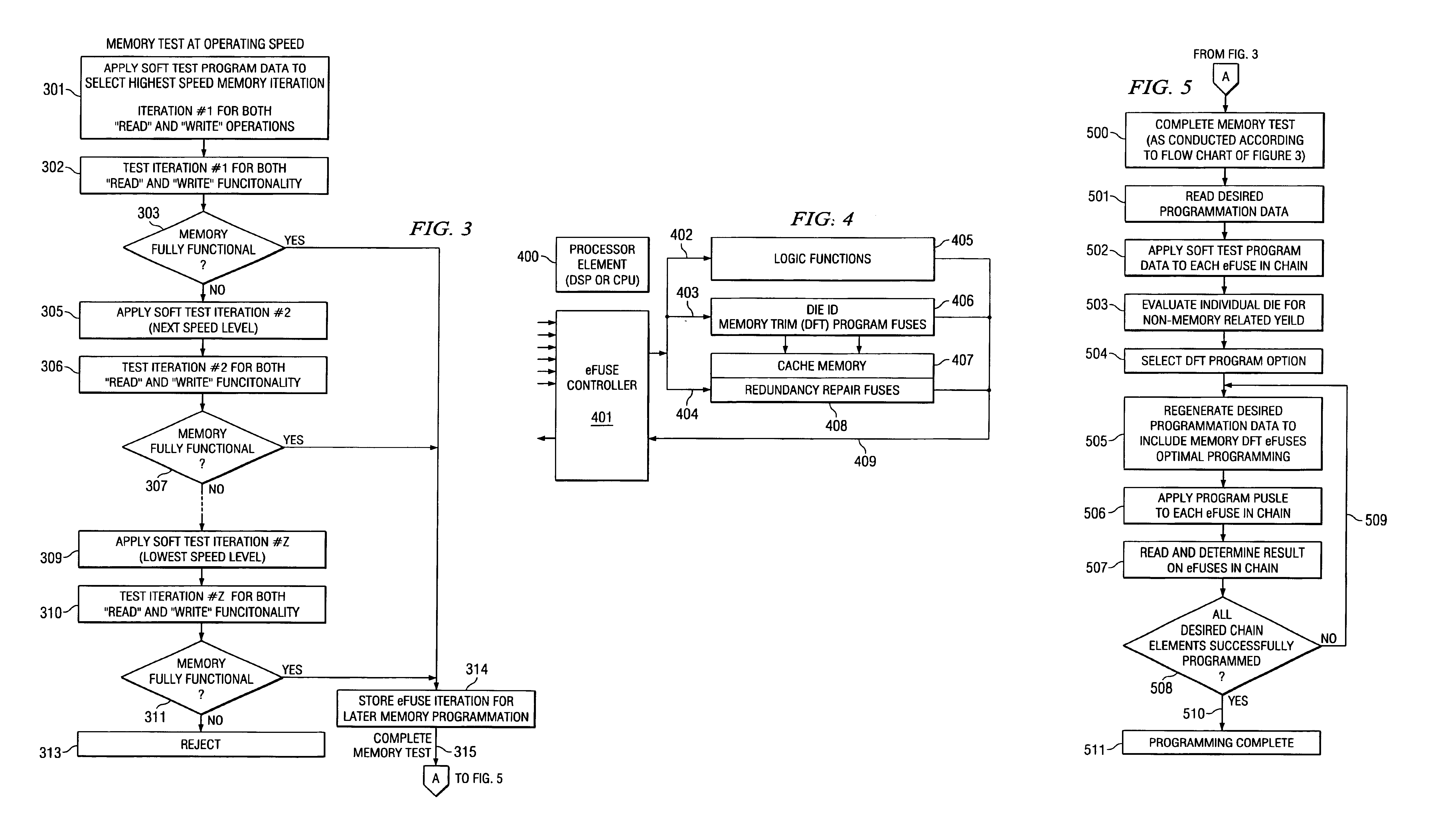
[0032]This invention describes the use of custom eFuse programming for recovery of potential memory yield loss in complex processor devices containing cache memory. This custom programming is better in cost and testing time than earlier techniques. The read and write operations associated with memories in complex processor devices sometimes need to be given additional margins in order to function properly. Process variations may cause the timing of the differential sense read circuits and the critically timed write circuit elements used in such memories to be outside the requirements for proper operation. In these situations, the memory can be made usable by increasing the memory timing. This leads to recovery of memory yield. This technique is referred to as the memory trimming or memory slow-down.

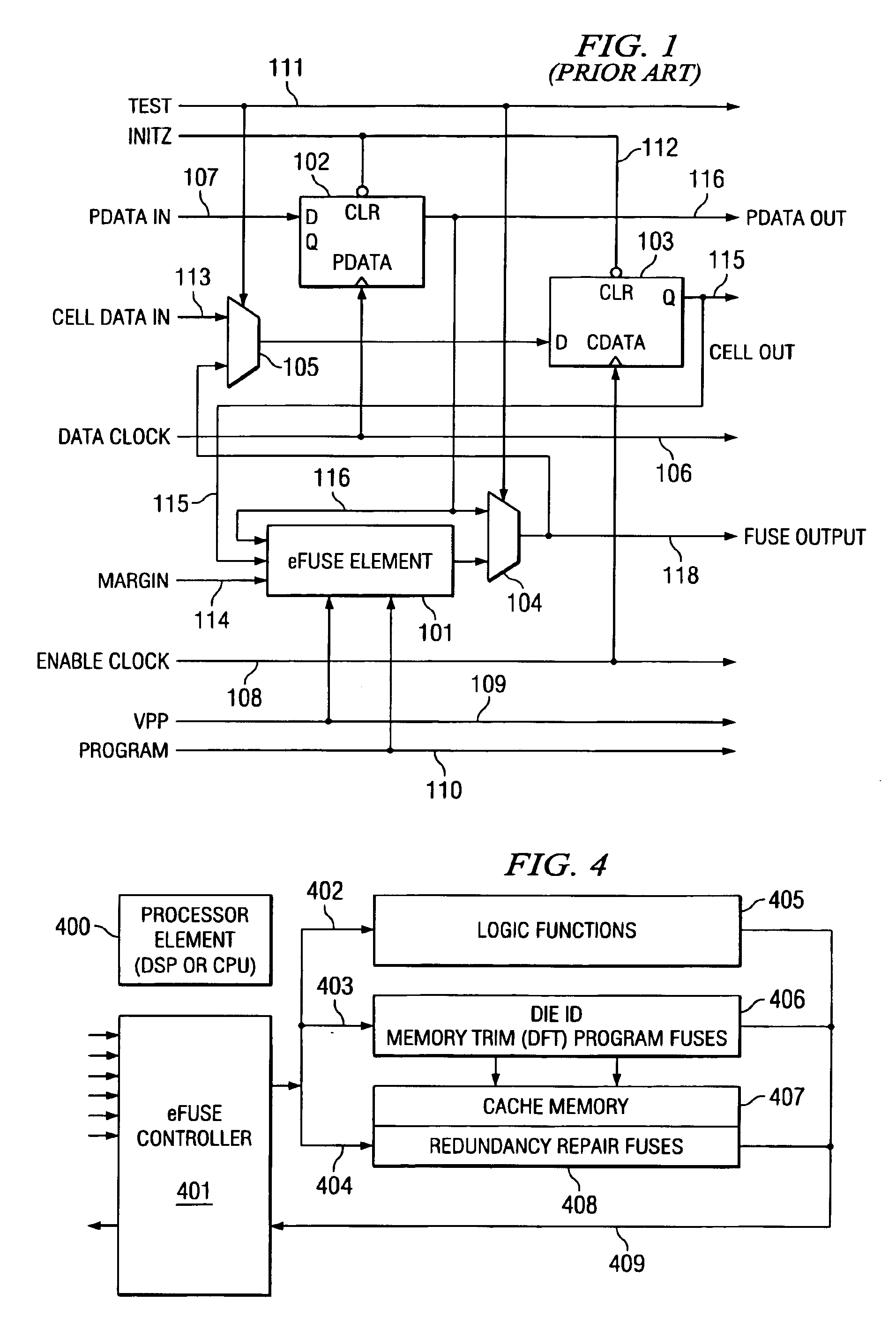
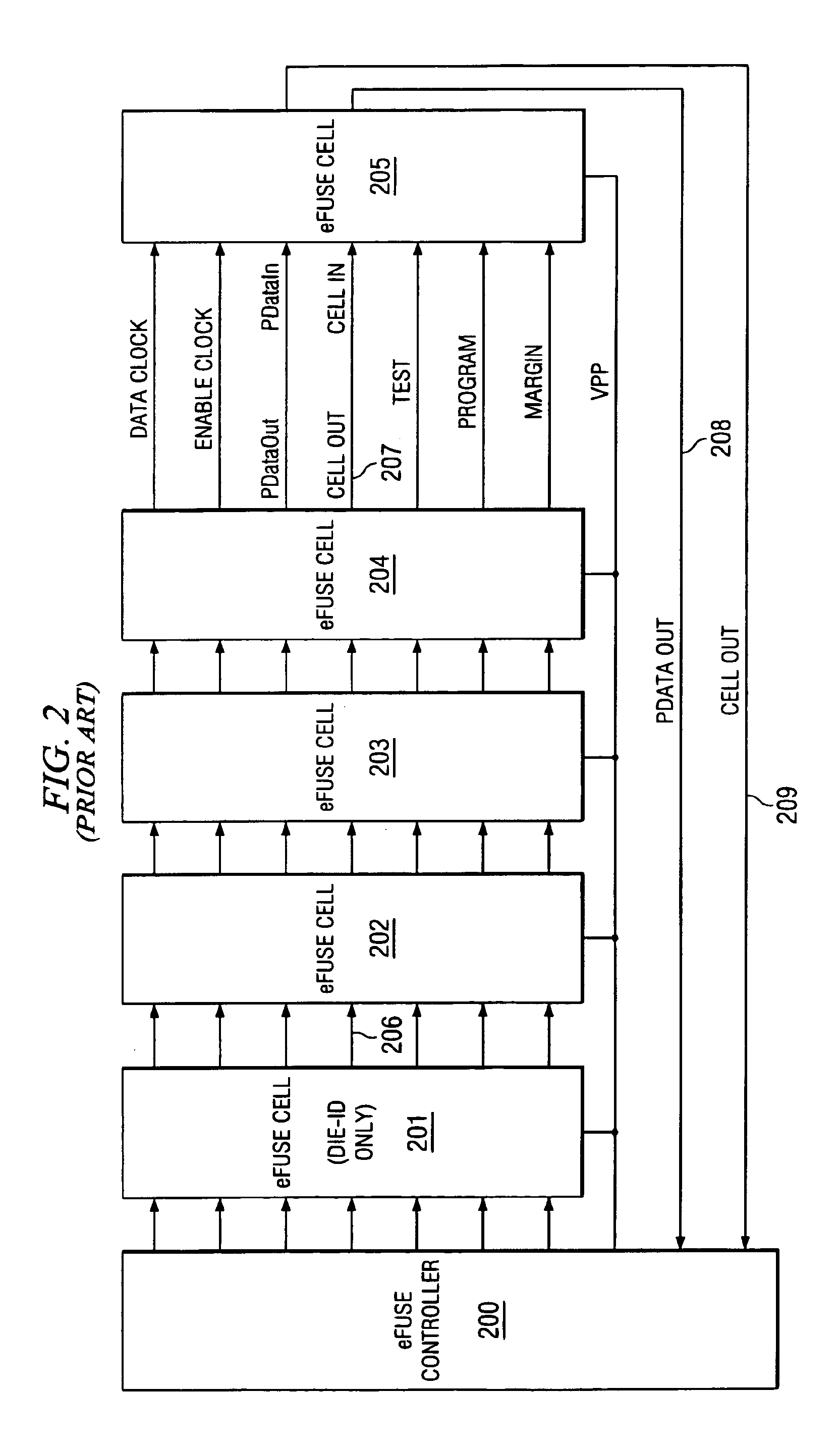
[0033]Electrical fuses (eFuse) are widely used for redundant RAM repair and die-identification (die-ID). Supplemental bits may be incorporated in the die-ID chain portion of the eFuse net...


PUM


Abstract

Electrical fuses (eFuses) are applied to the task of memory performance adjustment to improve upon earlier fuse techniques by not requiring an additional processing step and expensive equipment. Standard electrical fuse (eFuse) hardware chains provide a soft test feature wherein the effect of memory slow-down can be tested prior to actually programming the fuses. Electrical fuses thus provide a very efficient non-volatile method to match the logic-memory interface through memory trimming, drastically cutting costs and cycle times involved.

Description

TECHNICAL FIELD OF THE INVENTION[0001]The technical field of this invention is control of memory speed of operation on an integrated circuit including both a microprocessor and memory.BACKGROUND OF THE INVENTION[0002]Microprocessor chips fabricated with current CMOS technology are designed with great care to comprehend the circuit performance variations that occur as the process shifts from one tolerance extreme to the other. Designers have become accustomed to speak of MOS transistors having maximum drive capability as strong transistors and MOS transistors with minimum drive capability as weak transistors. At both of these extremes, the transistors are within specified process tolerance limits. It is desirable to maximize the useable yield of all functional devices even though different speed performance devices will be produced. Normally the whole performance distribution is salable.[0003]In practice, designs are analyzed according to (a) transistor strength, (b) power supply vol...

Claims


Application Information

Patent Timeline
Patent Type & Authority Patents(United States)
IPC IPC(8): G11C29/04G11C29/50
CPCG11C29/027G11C29/028G11C29/50G11C29/50012
Inventor KRISHNAN, MANJERISHEFFIELD, BRYANGRABER, JOEL J.LE, DUY-LOANAGARWALA, SANJIVE
Owner TEXAS INSTR INC
Learn More