Fiber optic cable having a strength member

a technology of fiber optic cables and strength members, which is applied in the field of fiber optic cables, can solve the problems of adding the cost of hardware such as the p-clamps and associated labor to install the same, and the optical fibers must be protected from the clamping force of the p-clamps, and achieve the effect of relieving stress

Inactive Publication Date: 2005-08-09
CORNING OPTICAL COMM LLC
View PDF22 Cites 31 Cited by
  • Summary
  • Abstract
  • Description
  • Claims
  • Application Information

AI Technical Summary

Benefits of technology

[0007]Additionally, the present invention is directed to a fiber optic cable having at least one optical waveguide, at least one strength member, and a jacket. The at least one strength member is a steel that is annealed for relieving stress induced in the manufacturing process.

Problems solved by technology

This drop cable installation has disadvantages such as added expense of hardware such as the P-clamps and associated labor to install the same.
Another disadvantage is that optical fibers must be protected from the clamping forces of the P-clamps.

Method used


Image

  • Fiber optic cable having a strength member
  • Fiber optic cable having a strength member
  • Fiber optic cable having a strength member

Examples


Embodiment Construction

[0011]The present invention will now be described more fully hereinafter with reference to the accompanying drawings showing preferred embodiments of the invention. The invention may, however, be embodied in many different forms and should not be construed as limited to the embodiments set forth herein; rather, these embodiments are provided so that the disclosure will fully convey the scope of the invention to those skilled in the art. The drawings are not necessarily drawn to scale but are configured to clearly illustrate the invention.

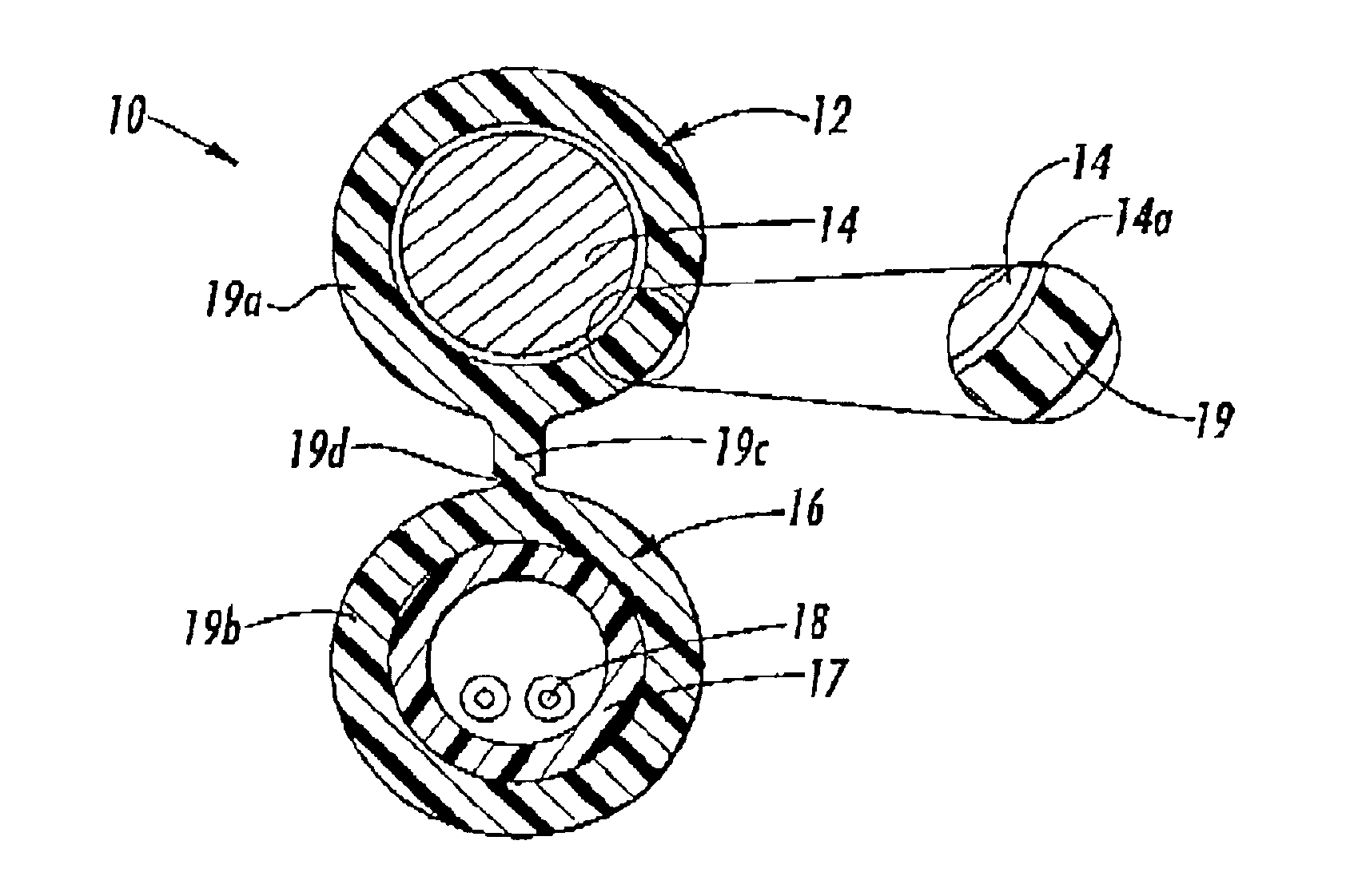
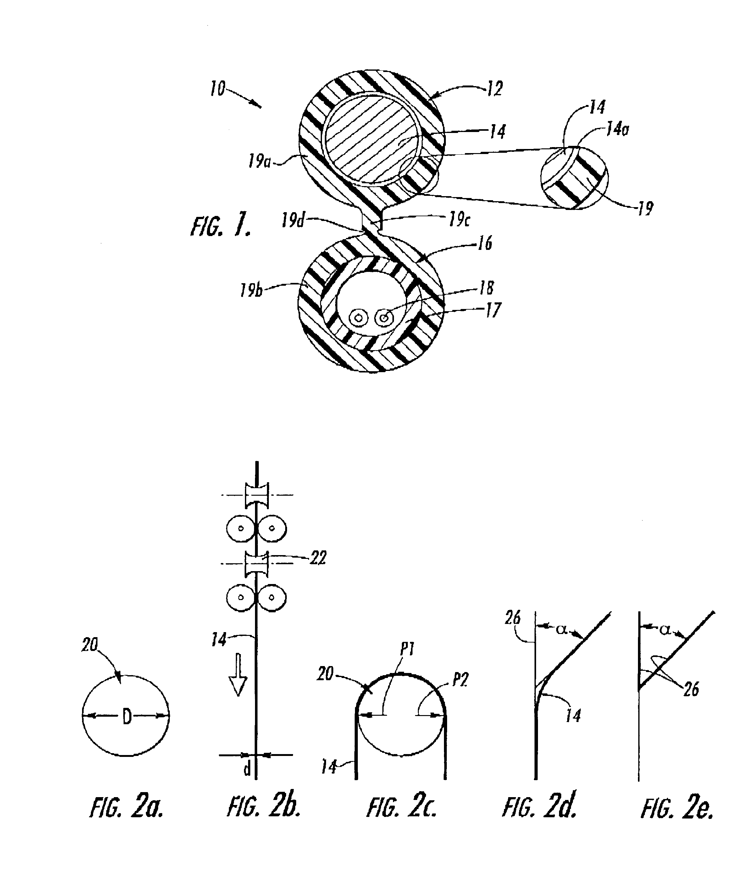
[0012]Illustrated in FIG. 1 is a fiber optic cable 10 according to one embodiment of the present invention. Fiber optic cable 10 (hereinafter cable) includes a messenger section 12 having at least one strength member 14, a carrier section 16 having at least one optical waveguide 18, and a jacket 19. Jacket 19 includes a part of a messenger jacket 19a and a part of a carrier jacket 19b connected by a web 19c in a figure eight design. In this case, st...


PUM


Abstract

A fiber optic cable includes at least one optical waveguide, at least one strength member, and a jacket. The at least one strength member is a material having an average residual angle in the range of about 30 degrees to about 65 degrees during a bending test using a mandrel having a wire ratio (D / d) of about 200. The strength member is suitable, if necessary, for self-attaching to studs, hooks, or the like by bending it therearound and is also suitable for hardware such as P-clamps or other grips. In other embodiments, strength member 14 is annealed to relieve work hardening. Preferred embodiments use a steel strength member with a carbon content between about 0.30 percent to about 0.75 percent. Additionally, a coating may be applied to the strength member for environmental / corrosion protection or conductivity.

Description

FIELD OF THE INVENTION[0001]The present invention relates generally to fiber optical cables. More specifically, the invention relates to fiber optic cables having one or more strength members with given properties.BACKGROUND OF THE INVENTION[0002]Fiber optic cables include optical waveguides such as optical fibers that transmit optical signals, for example, voice, video, and / or data information. As businesses and households demand increased data capacity, fiber optic cables can eventually displace electrical voice, video, and data signal carriers. This demand will require low fiber count optical cables to be routed to end users, for example, businesses and households.[0003]Fiber optic cables can typically be used in various applications. For example, fiber optic drop cables can be suitable for both aerial and buried cable applications. More specifically, a fiber optic drop cable can be strung between poles, strung between a pole and the premises, and / or buried in the ground before r...

Claims


Application Information

Patent Timeline
Patent Type & Authority Patents(United States)
IPC IPC(8): G02B6/44H04N5/91
CPCG02B6/4422G02B6/4429G02B6/44
Inventor MOHLER, JAMES D.DUNN, KENNETH F.SEDDON, DAVID A.JACKMAN, WILLIAM S.
Owner CORNING OPTICAL COMM LLC
Why Eureka
Try Eureka