Finishing apparatus

a technology of finishing apparatus and detector, which is applied in the direction of electrographic process apparatus, thin material handling, instruments, etc., can solve the problems of increasing the cost, difficult to place a plurality of detectors corresponding to the types of record sheets on the design, and difficulty in dealing with different types of record sheets having close sheet sizes, etc., to achieve the effect of quick and easy finishing

Inactive Publication Date: 2005-08-09
FUJIFILM BUSINESS INNOVATION CORP
View PDF9 Cites 87 Cited by
  • Summary
  • Abstract
  • Description
  • Claims
  • Application Information

AI Technical Summary

Benefits of technology

[0012]It is therefore an object of the invention to provide a finishing apparatus including a finisher for making it possible to easily and rapidly finish for record sheets different in sheet size.
[0022]Preferably, the mark sensor 7 is placed in the punching unit 5 as in the example. If the punching unit 5 thus includes the mark sensor 7, mark detection and punching a hole are performed at an extremely near distance, so that variations in punched hole positions can be suppressed.
[0023]In such technical means, preferably the record position of the mark M for determining the punch position is in one margin at the center of the record sheet 2 in the width direction thereof and in the proximity of the punch position, for example. If the mark M is thus recorded at the center of the record sheet 2 in the width direction thereof and is detected by the mark sensor 7, a hole can be punched with the width direction center of the record sheet 2 as the reference, so that variations in punched hole positions can be suppressed and high accuracy can be provided.
[0024]Further, as another mode of the record position of the mark M, preferably the mark M is recorded at the punch position in the record sheet 2, for example. If the mark M is thus recorded at the punch position, the mark M is also removed at the hole punching time and thus is not left on the record sheet 2, so that the record sheet 2 can be held in good quality.

Problems solved by technology

In such a form, however, a plurality of detector need to be provided and therefore in addition to an increase in the cost, it becomes difficult to deal with different types of record sheets having close sheet sizes, and it is difficult on design to place a plurality of detector corresponding to the types of record sheets.
According to the form, only one detector is needed and therefore the above-mentioned problem of an increase in the cost is eliminated, but it is necessary to reciprocate the puncher for each record sheet so as to match the size of the record sheet, and a technical problem of incompatibility with a high-speed machine and incapability of realizing high productivity occurs.
Particularly, this technical problem becomes more noticeable as the record sheet size is smaller.

Method used


Image

  • Finishing apparatus
  • Finishing apparatus
  • Finishing apparatus

Examples


first embodiment

(First Embodiment)

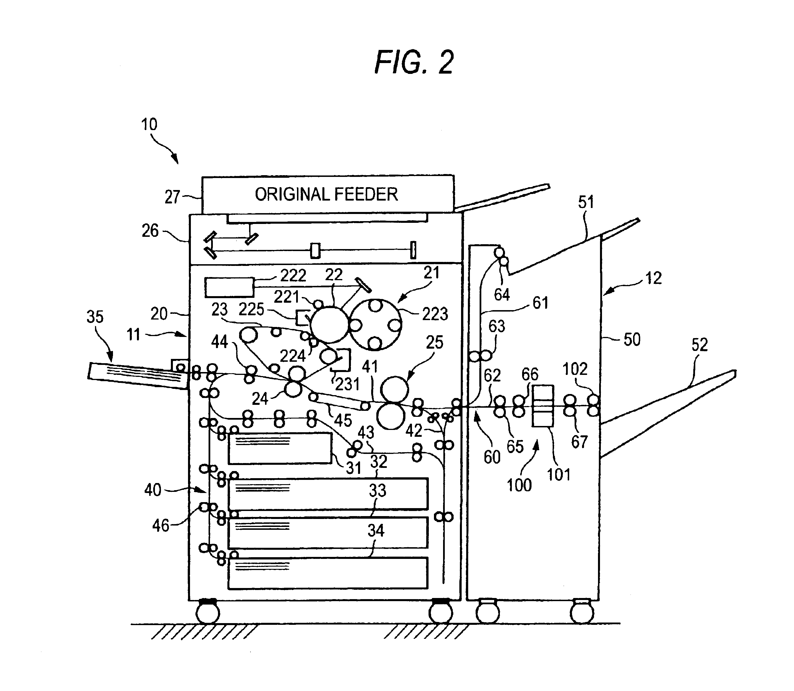
[0037]FIG. 2 is a schematic representation to show a first embodiment of a finishing apparatus incorporating the invention.

[0038]In the figure, a finishing apparatus 10 includes an image forming apparatus 11 capable of forming a color image and a finisher 12 for predetermined finishing for a record sheet S on which an image is formed.

[0039]In the embodiment, the image forming apparatus 11 adopts a so-called center registration technique for transporting the record sheet S (not shown) with the width direction center as the reference and forming an image. The image forming apparatus 11 includes an image read unit (IIT: Image Input Terminal) 26 being disposed on the top of a apparatus main unit 20 for reading an original, an original feeder 27 being disposed above the image read unit (IIT) 26 for feeding an original into the image read unit (IIT) 26, an image formation module 21 being disposed in the apparatus main unit 20, sheet supply trays 31 to 34 at multiple stag...

third embodiment

(Third Embodiment)

[0074]A finishing apparatus according to a third embodiment of the invention has a basic configuration roughly similar to that of the finishing apparatus according to the first embodiment; the third embodiment differs from the first embodiment in that the finishing unit 101 shown in FIG. 2 is a stapler for stapling a record sheet S and in particular intended for dual staple.

[0075]Since the third embodiment is intended for dual staple, as the record position of a mark M for determining a staple position, a similar configuration to that in the second embodiment may be adopted.

[0076]The third embodiment also provides roughly similar advantages to those of the first or second embodiment.

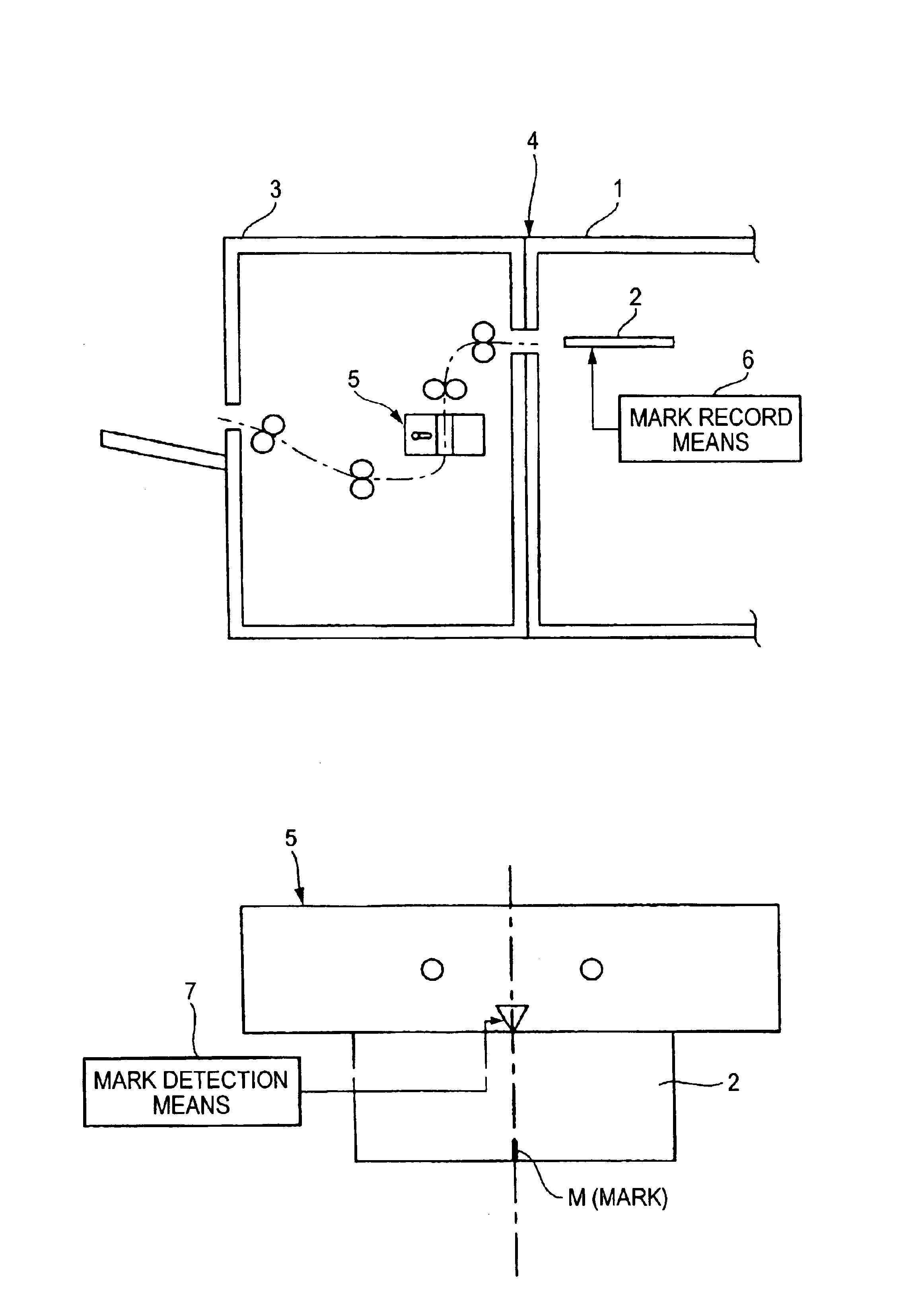
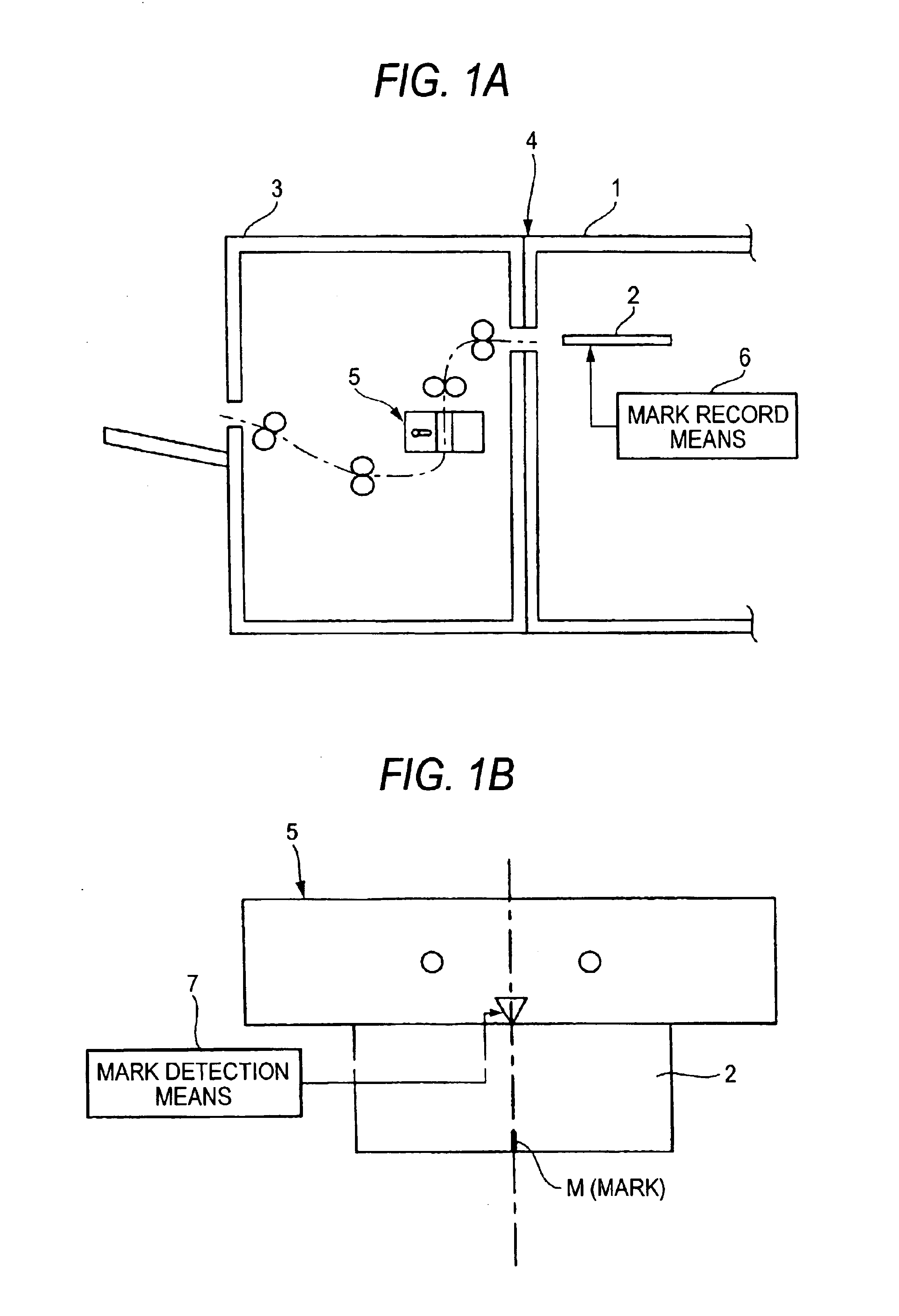
[0077]As described above, according to the invention, the finishing apparatus includes the mark recorder for recording a mark to determine the punch position on a record sheet before punching, so that the punch position can be determined simply by detecting the mark and it is made possi...


PUM


Abstract

A finishing apparatus 4 has an image forming apparatus 1 for forming an image by an image formation module and a finisher 3 for finishing for a record sheet 2 on which an image is already formed from the image forming apparatus 1. The finisher 3 has a punching unit 5 for punching a hole in the record sheet 2. The finishing apparatus 4 further includes mark recorder 6 for recording a mark M to determine the punch position on the record sheet 2 before punching.

Description

BACKGROUND OF THE INVENTION[0001]This invention relates to a finishing apparatus including an image forming apparatus such as a copier, a printer, or a facsimile using electrophotography and a finisher for finishing for a record sheet on which an image is already formed from the image forming apparatus and in particular to an improvement in a finisher for performing predetermined punching or stapling for each record sheet.[0002]Hitherto, as this kind of finishing apparatus for performing punching, an apparatus including a punch mechanism (puncher) which previously moves to a predetermined position based on size information of a sheet-like member (record sheet) in a width direction there of and punching information indicating whether or not punching is to be performed wherein the puncher stands by at the position corresponding to a sheet-like member of the maximum width to which punching can be applied when punching is not performed has been proposed, for example, as disclosed in the...

Claims


Application Information

Patent Timeline
Patent Type & Authority Patents(United States)
IPC IPC(8): B65H37/04G03G15/00
CPCG03G15/6582G03G2215/00818
Inventor SAKUMA, AKIRA
Owner FUJIFILM BUSINESS INNOVATION CORP
Why Eureka
Try Eureka