
Alternating pressure pads

a technology of pressure pads and alternating pressure, which is applied in the direction of fluid mattresses, sofas, transportation and packaging, etc., can solve the problems of constant loss of air from the system, and achieve the effect of easy cleaning and disinfection of the surfa

Inactive Publication Date: 2005-08-16
HUNTLEIGH TECH LTD
View PDF9 Cites 89 Cited by
  • Summary
  • Abstract
  • Description
  • Claims
  • Application Information

AI Technical Summary

Benefits of technology

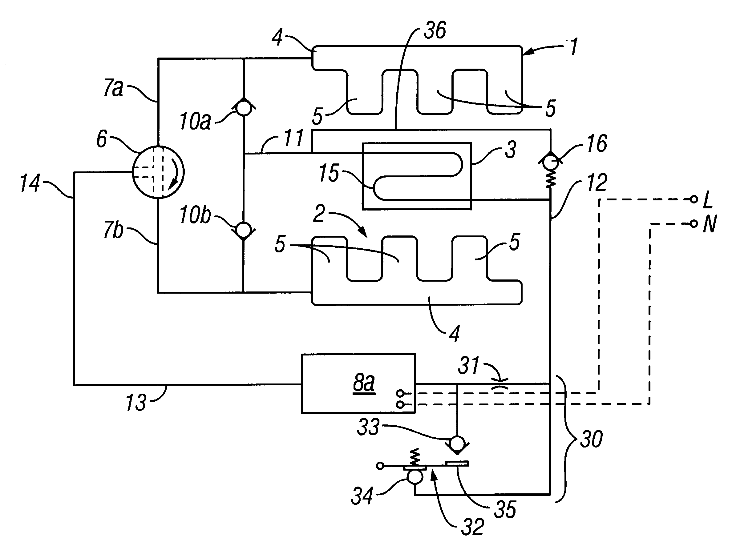
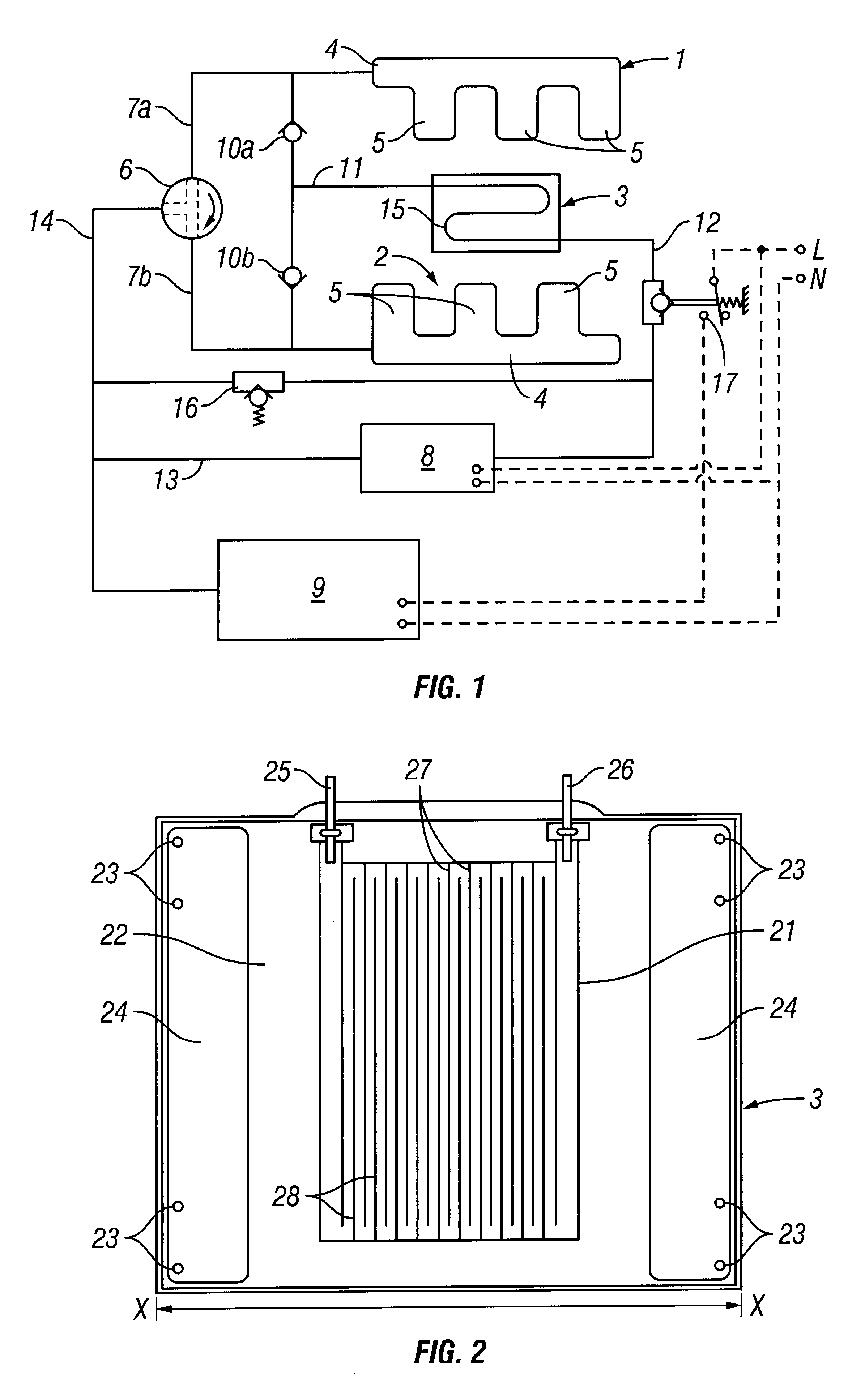
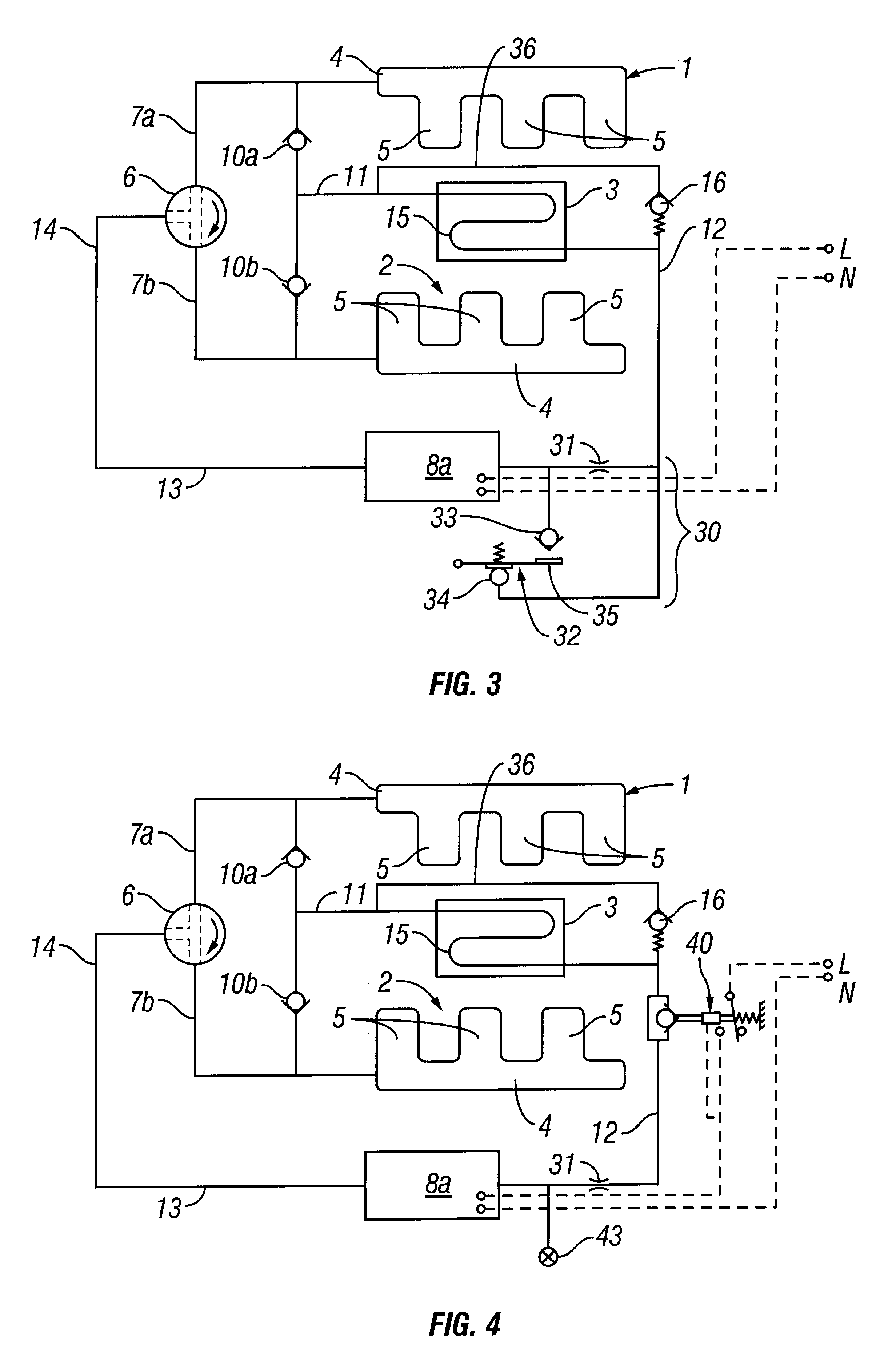
[0006]According to another aspect of the present invention, therefore, there is provided an alternating pressure pad which comprises at least two sets of inflatable cells, an air supply line to each set, a pump to alternately circulate pressurized air through a circuit including the sets of cells and to return air from the cells to the pump, the sensor pad in said circuit through which pressurized air is passed and a detecting means for detecting a reduction below a predetermined level of air flow through the sensor pad and for increasing air pressure in said sets of cells to restore the air flow to above said predetermined level.
[0011]Preferably, the inflatable cells are arranged in at least two sets of interposed cells, e.g. an interdigitated arrangement as described in U.S. Pat. No. 5,396,671. Conveniently, there are one or more layers of interdigitated cells, preferably contained within a cover that is waterproof and provides an easily cleaned and disinfected surface. Such an arrangement is described in the above U.S. patent and has the advantage that if the cells in the two or more layers are disposed such that a deflating cell is juxtaposed beneath or above an inflating cell, the user of the mattress is less likely to touch the underlying support surface during any part of the alternating cycle.

Problems solved by technology

While simple in operation, a sensor tube of this kind has the disadvantage that there is a constant loss of air from the system which necessitates the continuous operation of a higher capacity pump than would be required if such a leak could be avoided.

Method used


Image

  • Alternating pressure pads
  • Alternating pressure pads
  • Alternating pressure pads

Examples


Embodiment Construction

[0019]Although those of ordinary skill in the art will readily recognize many alternative embodiments, especially in light of the illustrations provided herein, this detailed description is exemplary of the preferred embodiment of the present invention, the scope of which is limited only by the claims appended hereto.

[0020]Referring to FIG. 1, the alternating pressure pad comprises two sets 1 and 2 of inflatable cells. These cells are preferably constructed as longitudinal headers 4 and interdigitated finger-like cells 5 having a form as described in U.S. Pat. No. 5,396,671. A sensor pad 3 is positioned to lie beneath the mattress formed by the sets 1 and 2. The inflatable sets 1 and 2 are connected to a rotary valve 6 by air input lines 7a and 7b. Rotary valve 6 is fed with air from low power circulation pump 8 or larger powered main inflation pump 9.

[0021]Circulation pump 8 may be a diaphragm pump having a relatively low output capacity, whereas main inflation pump 9 may be an axi...


PUM


Abstract

An alternating pressure pad comprises at least two sets of inflatable cells, an air supply line to each set, a pump to circulate pressurized air through a circuit including the sets of cells and to return air from the cells to the pump, valve means for alternately causing inflation and deflation of each set, a sensor pad in the circuit through which pressurized air is passed and detecting means for detecting a reduction in air flow through the sensor pad to a level below a predetermined level and for increasing air pressure in the sets of cells to restore the air flow to a level above the predetermined level.

Description

RELATED APPLICATIONS:[0001]This application is a continuation of PCT international application Ser. No. PCT / GB96 / 02895 filed Nov. 25, 1996, which designates the United States and claims priority to British patent application No. 9523990.1 filed Nov. 23, 1995 and British patent application No. 9525814.1 filed Dec. 18, 1995.FIELD OF THE INVENTION[0002]The present invention relates to alternating pressure pads. More particularly, the invention relates to alternating pressure pads for use in nursing patients and others prone to bed sores.BACKGROUND OF THE INVENTION[0003]Alternating pressure pads are known and have been used in the construction of mattresses, chairs, couches and other patient support devices to improve blood circulation, and thereby reduce the incidence of bed sores.[0004]U.S. Pat. No. 5,396,671 discloses an alternating pressure pad particularly designed for use as a mattress, in which two sets of inflatable cells are alternately inflated and deflated in order to stimula...

Claims


Application Information

Patent Timeline
IPC IPC(8): A47C27/08A61G7/057
CPCA61G7/05776A61G2203/34
Inventor STACY, PETER CHARLES
Owner HUNTLEIGH TECH LTD
Learn More