
Banding packing machine

a packing machine and banding technology, applied in the field of banding packing machines, can solve the problems of increased cost, insufficient length, and a large amount of for

Inactive Publication Date: 2005-08-16
STRAPACK SHIMOJIMA CO LTD
View PDF26 Cites 4 Cited by
  • Summary
  • Abstract
  • Description
  • Claims
  • Application Information

AI Technical Summary

Benefits of technology

[0015]In consideration of such actual circumstances, it is an object of the present invention to provide a banding packing machine capable of inexpensively detecting the end of a band reel and contributing to a reduction in a cost.
[0029]If the rotating speed is detected by the proximity switch, thus, the structure can easily be obtained inexpensively.
[0042]According to the present invention having such a structure, the same functions as those in the aforementioned banding packing machine are fulfilled. In addition, the following functions and advantages can be obtained.
[0052]In the banding packing machine according to the present invention, it is possible to detect the end of the band reel by simply detecting a change in the rotating speed of the touch roller. When the end of the band reel is to be detected, accordingly, a new structure is not required but it is sufficient that the rotating speed of the touch roller is still detected. Therefore, the number of components can be decreased and a cost can be reduced. In addition, this can be carried out by only electrical control. Consequently, the control can be performed very easily.
[0054]Moreover, the rotating speed of the driving means can easily be detected by the proximity switch.

Problems solved by technology

On the other hand, in the conventional banding packing machine, a great deal of force is required for directly pulling a band out of the band reel and feeding the band toward the band guide arch side.
In some cases in which the banding is to be newly carried out in the banding packing machine, however, the excess of the band stored in the pool box, particularly, in the back pool box causes a length to be insufficient.
Correspondingly, there is a problem in that a cost is increased.

Method used


Image

  • Banding packing machine
  • Banding packing machine
  • Banding packing machine

Examples


Embodiment Construction

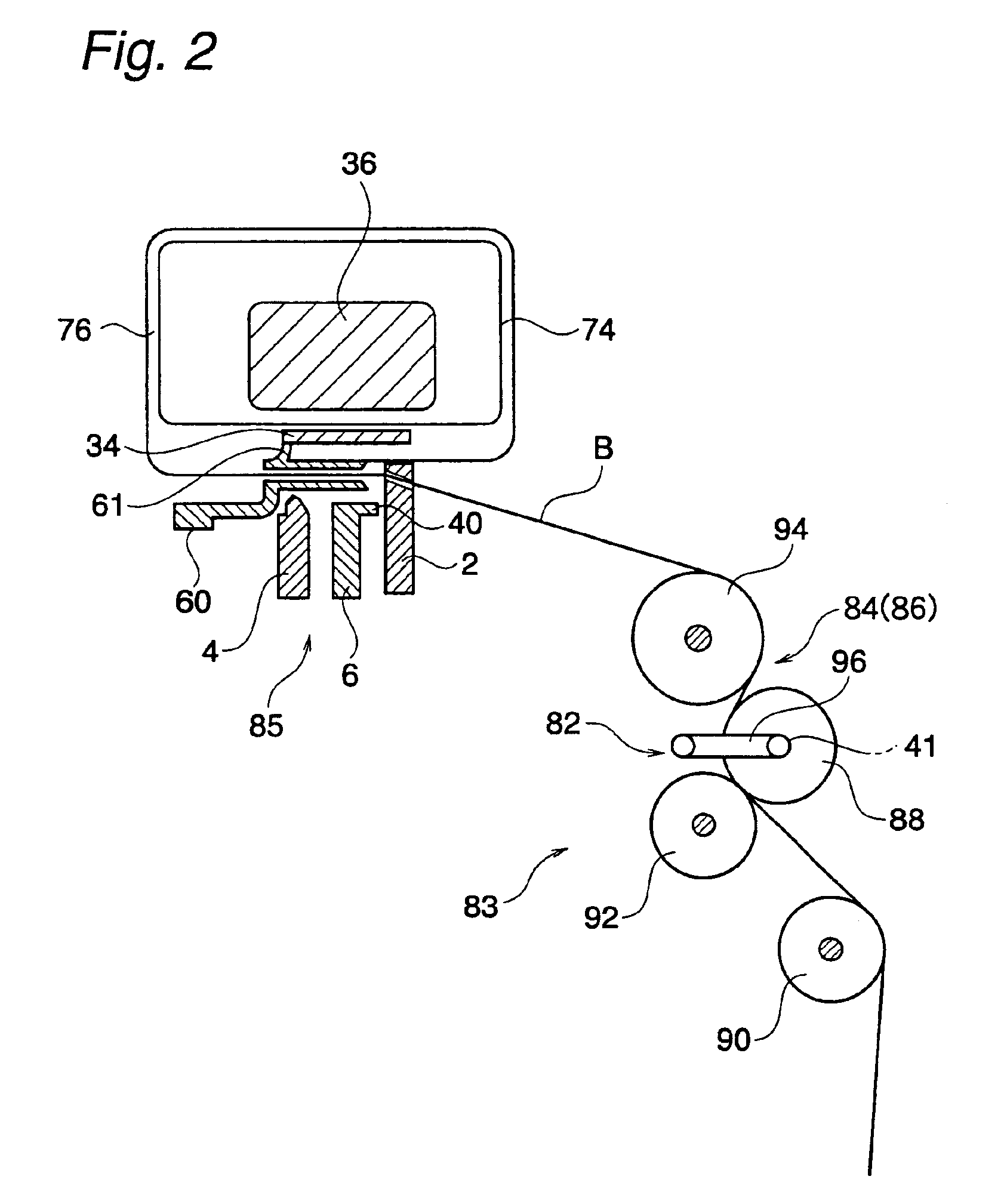
[0060]Several presently preferred embodiments of the present invention will be described below with reference to the drawings.

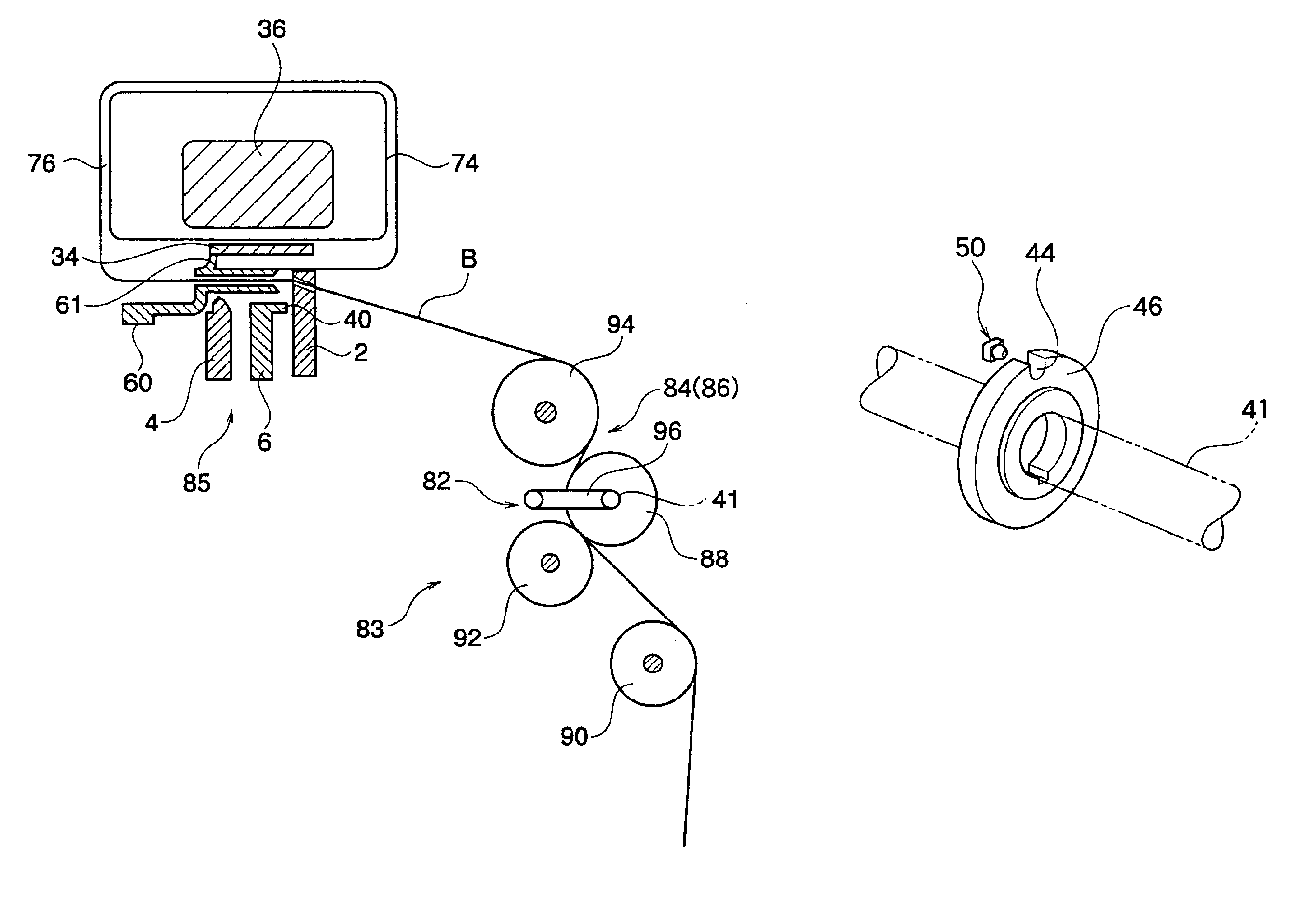
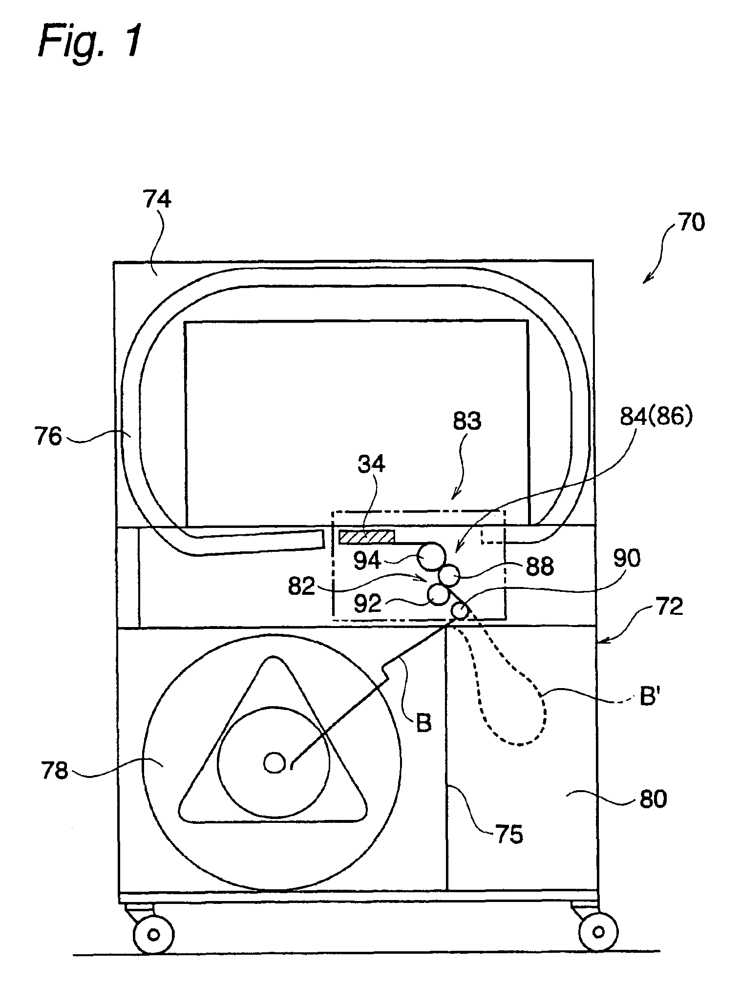
[0061]FIG. 1 shows a banding packing machine according to one presently preferred embodiment of the present invention.

[0062]In an automatic banding packing machine 70, an almost U-shaped band guide arch 74 is provided in the upper part of a packing machine body 72. In the band guide arch 74, a serial band passage 76 drawing a loop is formed over the packing machine body 72.

[0063]On the other hand, a band reel 78 is accommodated to be freely taken in / out of the left half part of the packing machine body 72 in FIG. 1. Moreover, a back pool box 80 is formed by a partition plate 75 in the right half part of the packing machine body 72. The back pool box 80 serves to temporarily accommodate the excess of a band B pulled back from the band guide arch 74 when banding is carried out. Accordingly, the amount of the band to be accommodated in the back pool box 80 is in...


PUM

PropertyMeasurementUnit
Speedaaaaaaaaaa

Abstract

A banding packing machine capable of inexpensively detecting the end of a band reel, thereby contributing to a reduction in cost. In a banding packing machine having a back pool box in a packing machine body and serving to feed an unused band (B) stored in the back pool box and a band from a band reel, the rotating speed of a touch roller is detected when a required amount of band is being pulled out of the band reel wherein the band is not left in the band reel if the rotating speed is not changed but the rotation is carried out at an almost constant speed, and the tip portion of the band does not arrive at the predetermined position of a band guide arch. Then, the driving operation of a normal rotating roller is stopped based on the decision signal.

Description

BACKGROUND OF THE INVENTION[0001]1. Field of the Invention[0002]The present invention relates to a banding packing machine, and more particularly to an automatic banding packing machine comprising a band guide arch and serving to automatically detect that a band is not left in a band reel and the band in the band reel is used up in a series of operations for feeding the band toward the band guide arch side and pulling back the band from the band guide arch.[0003]2. Description of the Related Art[0004]For example, some automatic banding packing machines accommodate, in a packing machine body, a band reel around which the band is wound in a large amount (Japanese Patent Application No. 2002-67089).[0005]In such a banding packing machine, the band reel is not protruded from the side surface of the packing machine body. Therefore, there is an advantage that a whole shape is small-sized.[0006]On the other hand, in the conventional banding packing machine, a great deal of force is require...

Claims


Application Information

Patent Timeline
IPC IPC(8): B65B13/22B65B13/18
CPCB65B13/22B65B13/184B65B13/18
Inventor SHIBAZAKI, TOKIOENDA, KENICHIAIZAWA, YOSHIKATSUTSURUMAKI, SABUROSATO, MITSURUOOFUKUJI, SHIGERUTOBITA, EIJIKUSUHATA, HIROHIKO
Owner STRAPACK SHIMOJIMA CO LTD
Learn More