Watertight protective carrying case

a protective carrying case and watertight technology, applied in the field of protective cases, can solve the problems of affecting the quality of protective carrying cases, allowing leakage at the containment area, and containing devices that are often unattractive, difficult and cumbersome to access, etc., and achieves the effect of convenient access and inexpensive production

Inactive Publication Date: 2005-08-16
FOAMTECH
View PDF13 Cites 53 Cited by
  • Summary
  • Abstract
  • Description
  • Claims
  • Application Information

AI Technical Summary

Benefits of technology

[0004]This invention provides a reliably watertight carrying case that is relatively impact and crush resistant, that provid...

Problems solved by technology

Such devices have not always provided for a tight seal due to uneven application of pressure by the mechanisms heretofore utilized to hold the container closed at the container segments' interface, thereby allowing leaks at the containment area.
In addition, such containing devices are often unattractive and/or difficult and cumbersome to access...

Method used


Image

  • Watertight protective carrying case
  • Watertight protective carrying case
  • Watertight protective carrying case

Examples


case 15

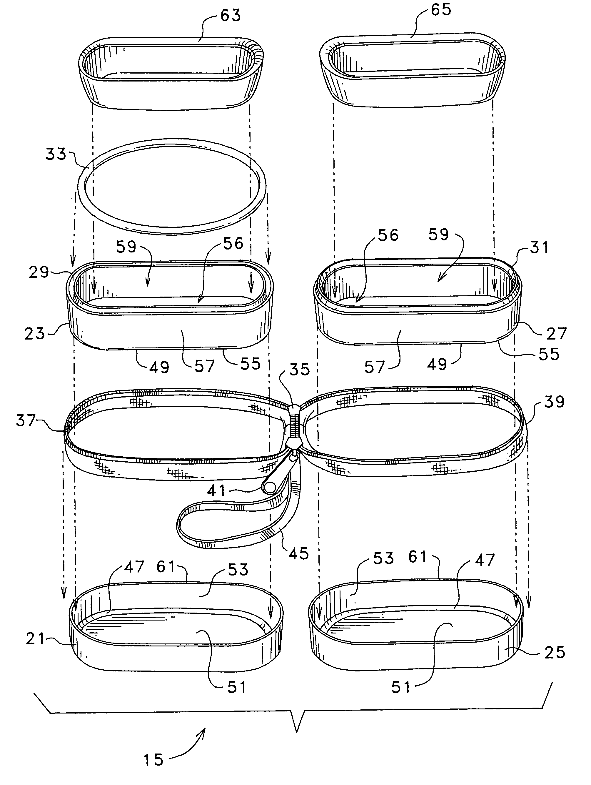
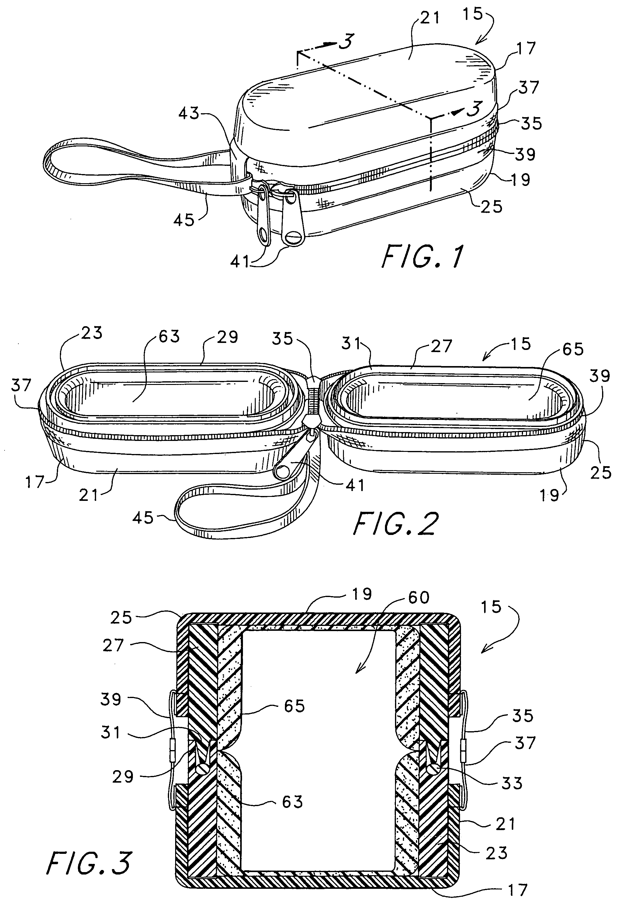
[0025]When case 15 is closed, with lips 29 and 31 mated, and sections 37 and 39 are engaged, cooperative closure 35 causes compression of sealing 33 in the groove of lip 29 by the tongue of lip 31. The compression thus effected by engagement of the closure sections is substantially constant at all locations along the interface of lips 29 and 31, and thus at sealing 33, thereby providing a quite efficacious seal of the entire interface with no need for closure 35 itself to be watertight. While a zipper-type closure is shown herein, other types of closures could be utilized (such as a ZIPLOC type of slide fastening system, or other types of securement systems capable of effecting the necessary constant application of compressive pressure when case 15 is closed).

[0026]Fabric hinge 43 and hand strap 45 are applied at outer containments 21 and 25 in this embodiment, though other applications may require other arrangements (hingeless, handles or the like).

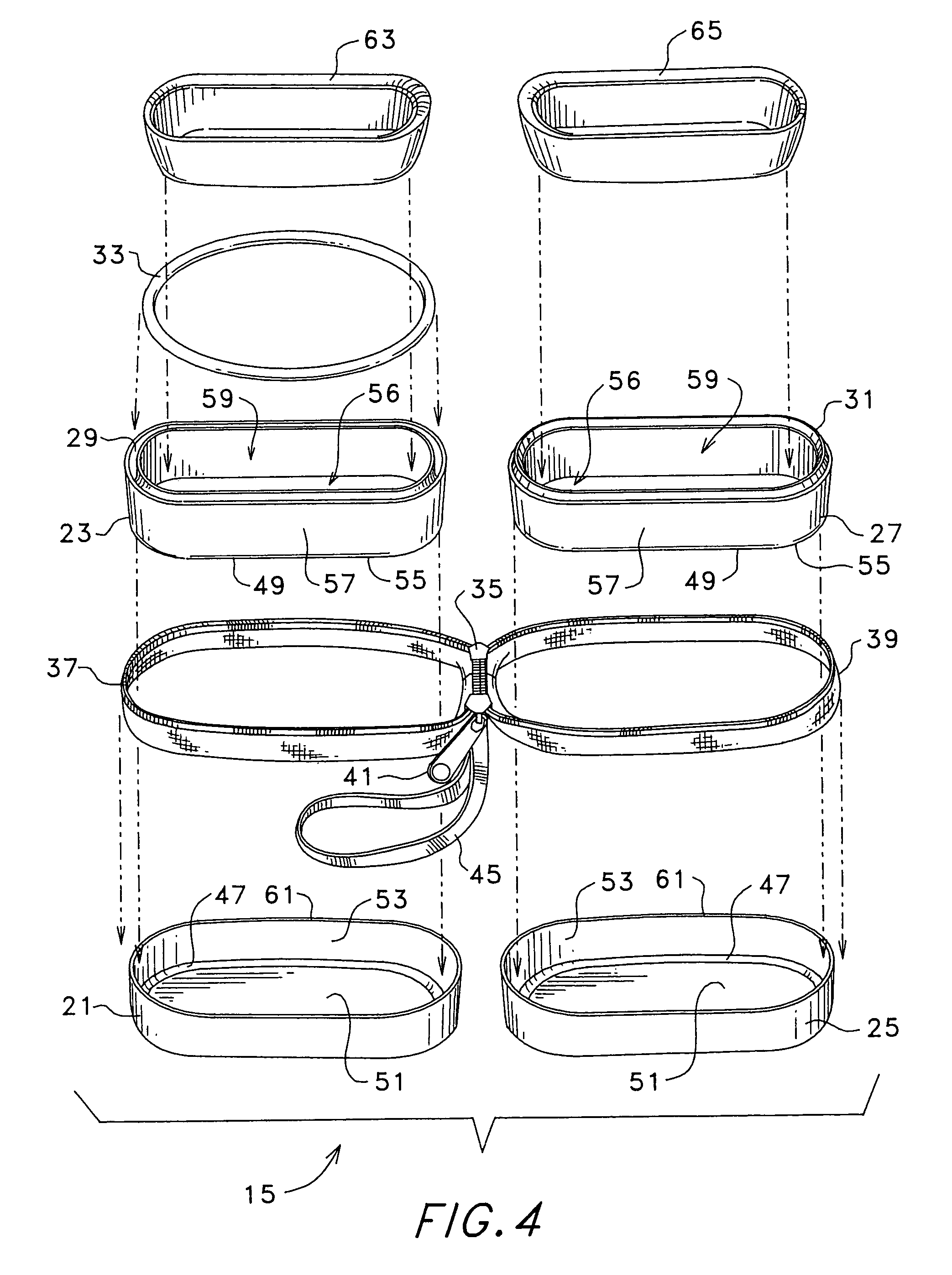
[0027]Turning to FIG. 4, the part...


PUM


Abstract

A watertight protective carrying case having first and second case body portions each including an outer containment and inner frame. Engageable lips are formed at one part of each inner frame, the lips matable in a sealing relationship when the case is in a closed condition. A cooperative closure assembly is configured and mounted at the outer containments so that upon engagement of the cooperative closure compressive pressure is applied at the frame lips with the engagable lips entirely enclosed by the cooperative closure. The compression thus effected by engagement of the closure is substantially constant at all locations along the interface of the lips thereby providing a tight seal of the entire interface with no need for the closure itself to be watertight.

Description

FIELD OF THE INVENTION[0001]This invention relates to protective cases, and, more particularly, relates to protective cases utilizing a watertight seal at their opening.BACKGROUND OF THE INVENTION[0002]A wide variety of sealable, watertight containing devices have heretofore been suggested and / or utilized. In particular, the use of various tongue and groove joints at container segments, with a sealing medium interposed therebetween, have been suggested, many of which make use of snaps, buckles, latches, or the like to cause compression sealing at the container joints (see, for example, U.S. Pat. Nos. 4,905,857, and 4,712,657). Some such devices have made use of multi-element structures, such as interposed multi-element rings between container body segments, to accomplish various desired structures (see, for example, U.S. Pat. Nos. 3,730,309, 3,088,623 and 2,515,715). Such devices have not always provided for a tight seal due to uneven application of pressure by the mechanisms hereto...

Claims


Application Information

Patent Timeline
IPC IPC(8): B65D85/38B65D81/07
CPCB65D81/07
Inventor SEAMANS, SCOTT A.
Owner FOAMTECH
Why Eureka
Try Eureka