Pipe fitting removal tool

a technology for removing tools and fittings, applied in the field of plumbing tools, can solve the problems of abs flange deformation under pressure, abs flange deformation and eventually breakage, steel flange rust and eventually breakage, etc., and achieve the effect of easy chemical bonding

Inactive Publication Date: 2005-08-16
DEVER CHRISTOPHER JOE
View PDF24 Cites 12 Cited by
  • Summary
  • Abstract
  • Description
  • Claims
  • Application Information

AI Technical Summary

Benefits of technology

[0010]The present invention provides both a method and an apparatus for removing a polymeric plastic plumbing fitting, such as a coupling or water closet flange from the pipe to which it is attached so that a new fitting or flange may be chemically bonded to the pipe. A preferred embodiment of the water closet flange removal tool includes an axial shaft, a cylindrical guide body attached to a lower end of the shaft, the guide body having an outer diameter slightly less than the inner diameter of the waste pipe so that it is slidably insertable therein, and a cylindrical-walled cutter, having an inside diameter slightly greater than the outer diameter of the waste pipe, mounted above the guide body. For a preferred embodiment of the tool, both the guide body and the cylindrical-walled cutter are coaxially mounted on the shaft. The cylindrical-walled cutter is open at the lower end thereof so that it can slide over the pipe as the flange is cut therefrom. In order to use the tool in the case were a water closet flange is removed from a waste pipe to which it has been chemically bonded, an upper end of the shaft is coupled to a drill motor, the guide body is inserted through the central opening of the flange and into the waste pipe. The shaft is then rotated with the drill motor. With the cutter rotating, the tool is driven further into the waste pipe until the flange is cut therefrom. The tool is then retracted and the flange discarded. For removing a closet flange that is embedded within concrete, the ideal thickness of the cylindrical-walled cutter is no greater than the thickness of the connector collar which attaches the flange to the waste pipe. For removing flanges and coupling which are not embedded within concrete, the thickness of the cylindrical-walled cutter may be greater than the thickness of the connector collar, thereby eliminating the need to completely cut through the collar in order to remove the flange. With very little touch up, the waste pipe can be prepared to receive the connector collar of a new water closet flange, which can be easily chemically bonded to the waste pipe. The invention eliminates the need for the splicing of pipes and structure damage that might be required to effect the splicing operation.

Problems solved by technology

However, after 1970, acrylonitrile-butadiene-styrene (ABS) plastic pipe rapidly replaced cast iron due to much lower material costs and greatly reduced installation costs.
A steel flange will eventually rust and break.
An ABS flange will deform under pressure and eventually break.
Consequently, water closet flanges which were installed in the 1970s are now requiring replacement.
However, if the pipe is embedded in concrete, replacement can be a major job requiring removal and replacement of concrete around the flange and around the waste pipe to which it is connected.
There are two problems with the design of the LaVanchy, et al. tool.
The first is a relatively high cost of manufacture.
The method of construction is relatively labor intensive, relatively complex, and requires a relatively high degree of precision for proper functionality.
The second problem with the LaVanchy, et al. tool is that the mounting of the separate cutter blades within the front-facing tubular portion of the body mandates that the thickness of the tubular portion be greater than the thickness of most closet hicker than must be of a thickness that is greater than the thickness of most closet flange couplers.
Thus, when a closet flange is embedded within a concrete slab, as is the case with most homes in the Southwestern, Southcentral and Southeastern states, the closet flange cannot be removed without the body of the tool striking the concrete.

Method used


Image

  • Pipe fitting removal tool
  • Pipe fitting removal tool
  • Pipe fitting removal tool

Examples


Embodiment Construction

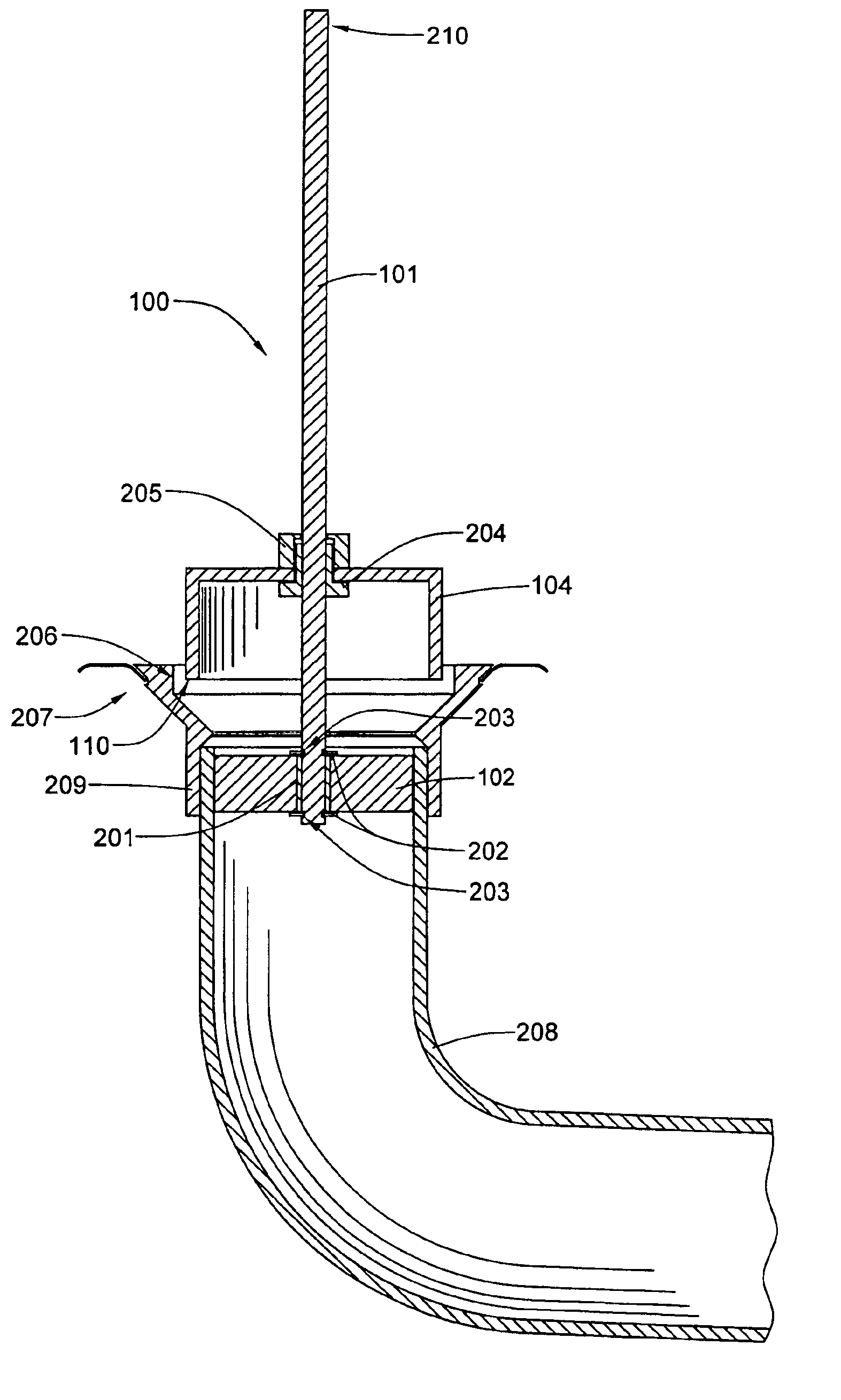
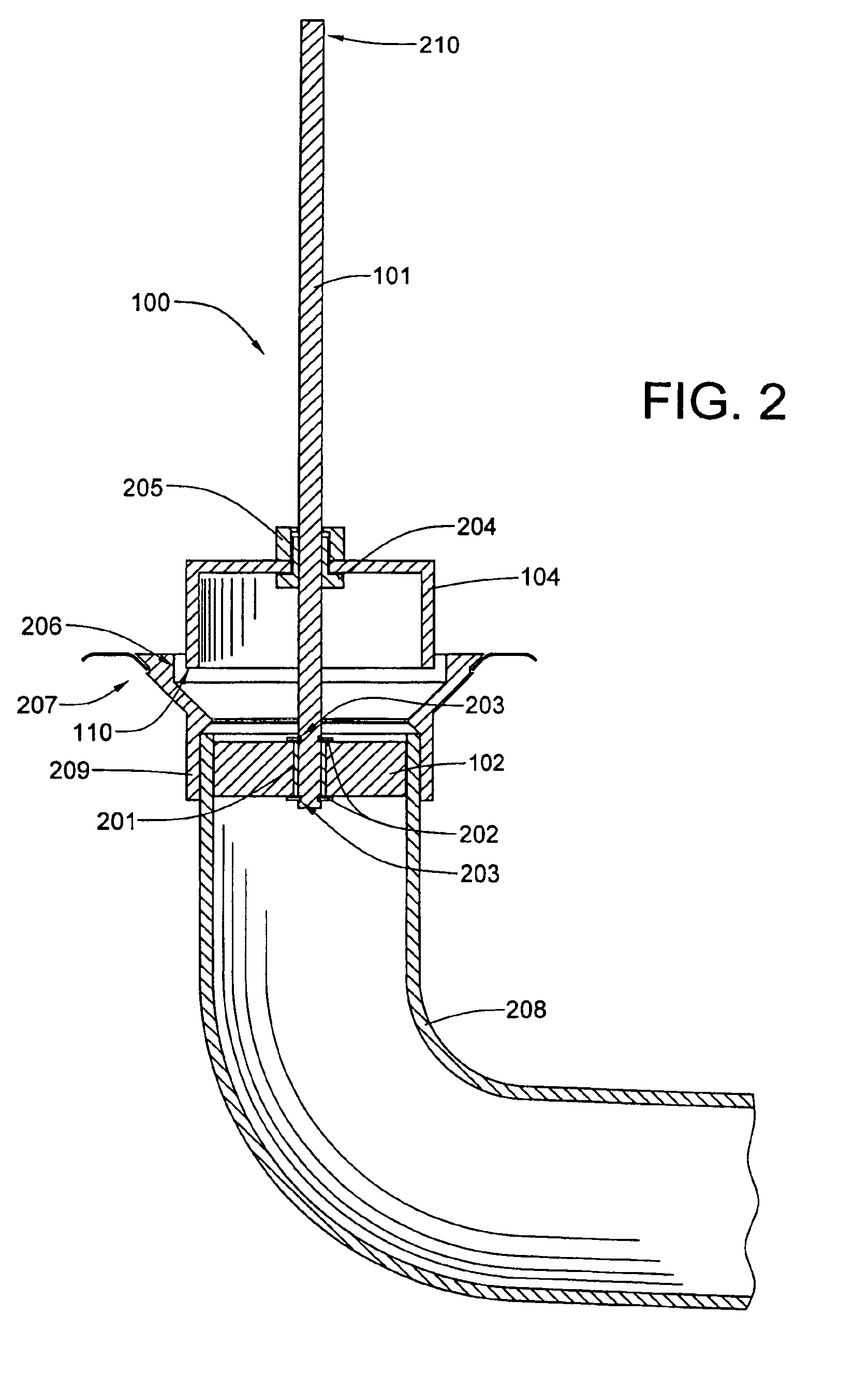
[0016]The present invention, which provides both a method and a tool for removing a pipe fitting made of polymeric plastic material from a pipe to which it has been chemically bonded. The pipe fitting removal tool and the process of removing a pipe fitting will now be disclosed in the context of removing a water closet flange from the waste pipe to which it is attached, with reference being made to the attached drawing figures.

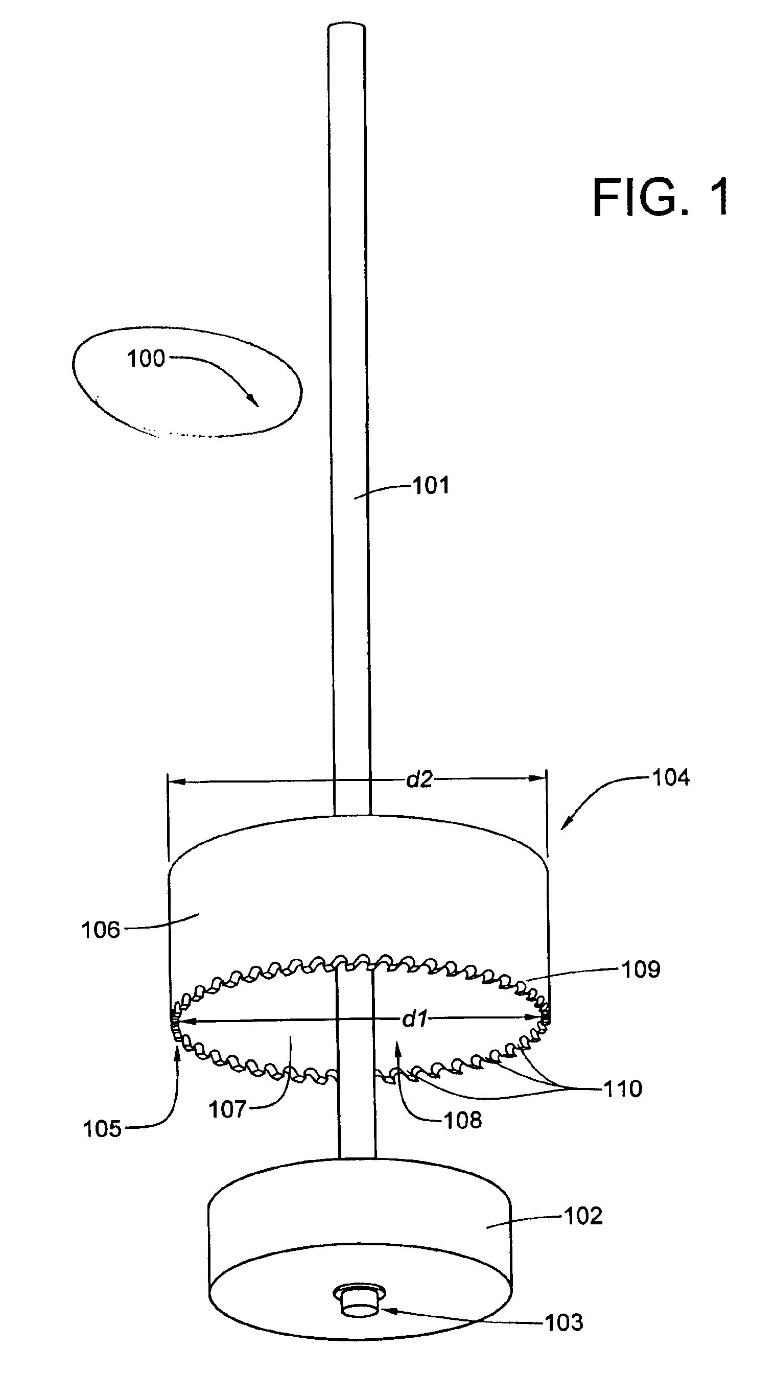
[0017]Referring now to both FIG. 1 and FIG. 2, a preferred embodiment of the tool 100 for removing a pipe fitting, such as a water closet flange, includes an axial shaft 101, a cylindrical guide body 102 attached to a lower end 103 of the shaft 101, the guide body having an outer diameter slightly less than the inner diameter of a water closet waste pipe so that it is slidably insertable therein, and a rotary cutter 104, having an inside diameter slightly greater than the outer diameter of the waste pipe, mounted above the guide body 102. The rotary cutter 104...


PUM

PropertyMeasurementUnit
diameteraaaaaaaaaa
outer diameteraaaaaaaaaa
pressureaaaaaaaaaa

Abstract

A method and tool are disclosed for removing a plastic water closet flange from the waste pipe to which it is attached so that a new flange may be chemically bonded to the existing waste pipe. A preferred embodiment of the water closet flange removal tool includes an axial shaft, a cylindrical guide body attached to a lower end of the shaft, the guide body having an outer diameter slightly less than the inner diameter of the waste pipe so that it is slidably insertable therein, and a cylindrical-walled cutter, having an inside diameter slightly greater than the outer diameter of the waste pipe, mounted above the guide body. For a preferred embodiment of the tool, both the guide body and the cylindrical-walled cutter are coaxially mounted on the shaft. The cylindrical-walled cutter is open at the lower end thereof so that it can slide over the waste pipe as the flange is cut therefrom. In order to use the tool, an upper end of the shaft is coupled to a drill motor, the guide body is inserted through the central opening of the flange and into the waste pipe. The shaft is then rotated with the drill motor. With the cutter rotating, the tool is driven further into the waste pipe until the flange is cut therefrom. The tool is then retracted and the flange discarded.

Description

[0001]This is a continuation-in-part of application Ser. No. 09 / 699,265, which was filed on Oct. 28, 2000, and is now abandoned.BACKGROUND OF THE INVENTION[0002]1. Field of the Invention[0003]This invention relates to plumbing tools and, more particularly to methods and apparatus for removing a plastic plumbing component that is chemically bonded to a mating component.[0004]2. Description of Related Art[0005]Until the late 1960s, cast iron pipe was used almost exclusively to convey sewer waste from residences and businesses to the main sewer line. Joints were packed with caulking rope and molten lead was poured into the joint to hold the caulking in place. However, after 1970, acrylonitrile-butadiene-styrene (ABS) plastic pipe rapidly replaced cast iron due to much lower material costs and greatly reduced installation costs. A water closet flange, a termination of the toilet waste pipe to which a toilet mounts, which originally had been a solid cast iron piece—replaceable by melting...

Claims


Application Information

Patent Timeline
Patent Type & Authority Patents(United States)
IPC IPC(8): B23B51/04
CPCB23B51/0426B23B2215/72Y10T408/03Y10T408/895Y10T408/8923Y10T408/558
Inventor DEVER, CHRISTOPHER JOE
Owner DEVER CHRISTOPHER JOE
Why Eureka
Try Eureka