Apparatus and method for treating containerized feed materials in a liquid reactant metal

a technology of liquid reactant metal and apparatus, which is applied in the direction of manufacturing converters, furnaces, nuclear engineering, etc., can solve the problems of providing contact time, disposing of collected waste materials, and either treating or disposing of containers which have themselves become contaminated

Inactive Publication Date: 2005-08-16
CLEAN TECH INT
View PDF37 Cites 20 Cited by
  • Summary
  • Abstract
  • Description
  • Claims
  • Application Information

AI Technical Summary

Benefits of technology

[0008]The present invention has the advantage that the containers of feed material can be treated as a unit and the feed material is preferably not released from the container prior to introducing the material into the liquid reactant metal. Feed material is reduced to innocuous compounds or elements. Hazardous elements such as radioactive elements and other metals are captured in the liquid reactant metal or in a slag in the reactor. The containers themselves are also destroyed either by chemical reduction in the case of plastic or paper containers, or by melting or dissolution in the case of metal containers.

Problems solved by technology

Very large quantities of some types of wastes have collected in storage because there has simply been no viable disposal alternative.
Containerized wastes not only present the problem of disposing of the collected waste material itself, but also present the problem of either treating or disposing of the containers which have themselves become contaminated.
A consistent issue in waste treatment processes utilizing a bath of a liquid reactant metal is ensuring sufficient contact between the liquid reactant metal and the waste material itself or intermediate compounds generated from initial reactions between the waste material and liquid reactant metal.
The problem of providing the required contact time is particularly acute with gaseous or volatile materials because such materials quickly separate from the liquid reactant metal and produce a bubble at the top of the liquid reactant metal container.

Method used


Image

  • Apparatus and method for treating containerized feed materials in a liquid reactant metal
  • Apparatus and method for treating containerized feed materials in a liquid reactant metal
  • Apparatus and method for treating containerized feed materials in a liquid reactant metal

Examples


Embodiment Construction

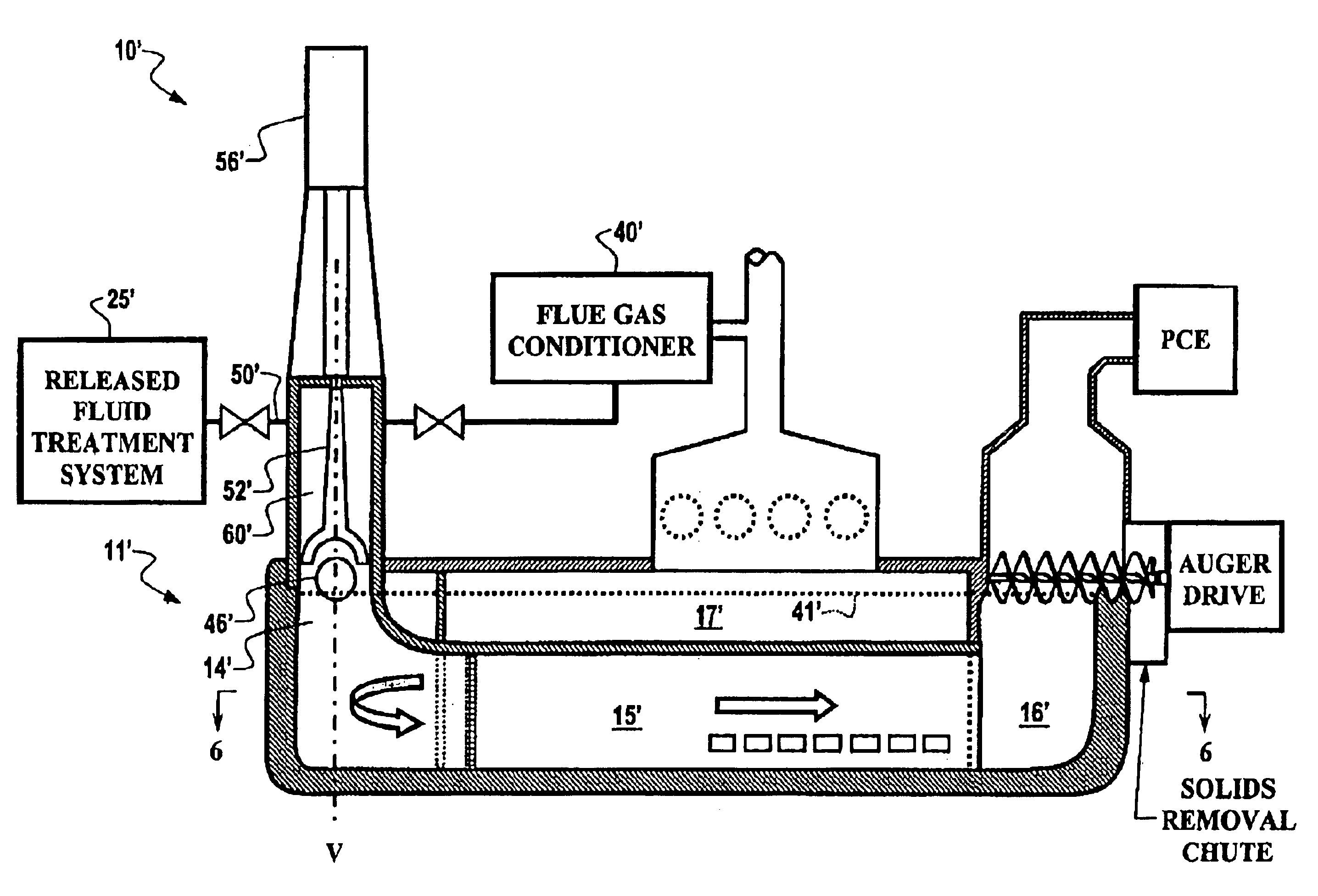
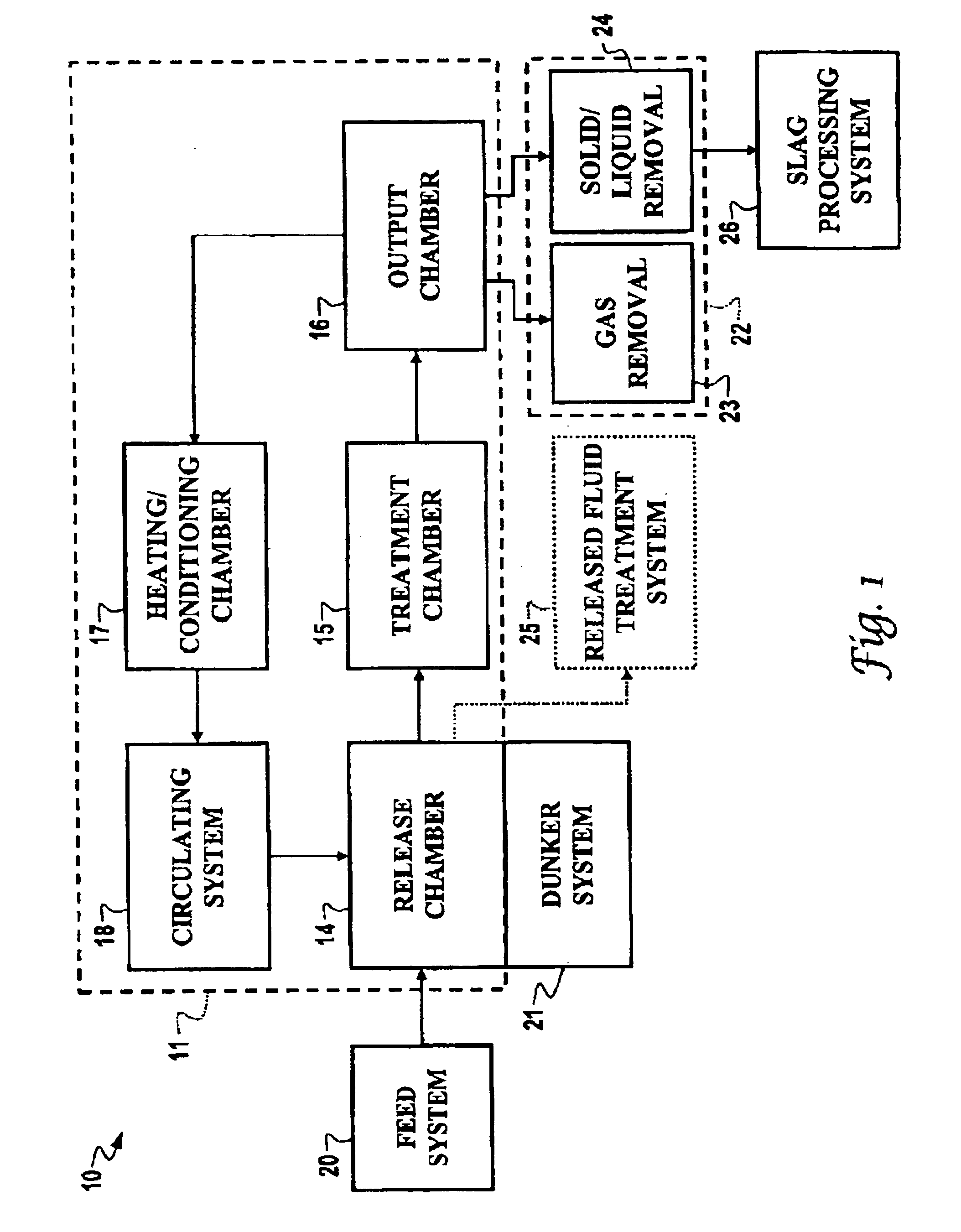
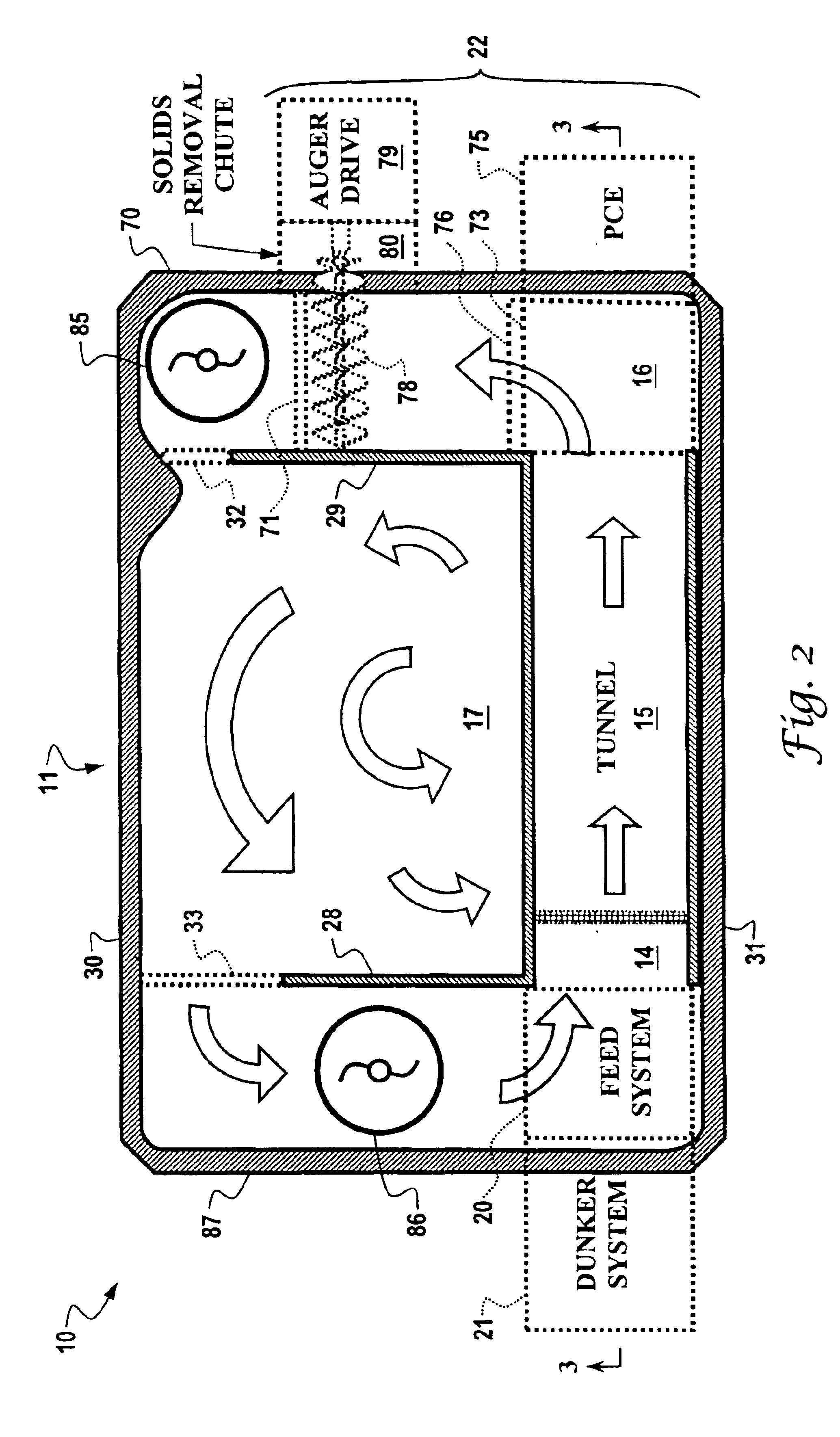
[0023]Referring to FIG. 1, a liquid reactant metal treatment apparatus 10 embodying the principles of the invention includes a liquid reactant metal containment vessel indicated by dashed box 11. Several different chambers or systems are contained or defined within containment vessel 11. In particular, containment vessel 11 encompasses a release chamber 14, a treatment or retention chamber 15, an output chamber 16, a heating and conditioning chamber 17, and a circulating system 18. Apparatus 10 also includes a feed system 20 for feeding material to be treated into the containment vessel 11, a dunker or submerging system 21 for dunking material to be treated under the surface of the liquid reactant metal in or adjacent to release chamber 14, and a reaction product removal arrangement 22 including a gaseous reaction product removal component 23, and a solid / liquid reaction product removal component 24. All of these basic components are included in both the form of the invention shown ...


PUM

PropertyMeasurementUnit
temperaturesaaaaaaaaaa
feed areaaaaaaaaaaa
areaaaaaaaaaaa

Abstract

A treatment apparatus (10) includes a liquid reactant metal containment vessel (11) for containing a first liquid reactant metal and isolating the reactant metal from the atmosphere. A release chamber (14) is adapted to receive the first liquid reactant metal from the containment vessel (11) and a submerging arrangement (21) is adapted to dunk or submerge a container (46) of feed material into the liquid reactant metal and move the container to a release location within the release chamber (14). Relatively light materials rising from the submerged container (46), including unreacted feed material, intermediate reaction products, and perhaps final reaction products collect in a collection area (60) having an upper surface defined by an upper surface of the release chamber (14). A treatment arrangement included in the apparatus places the fluids collected in the collection area (60) in contact with the first liquid reactant metal or a second liquid reactant metal for a sufficient period of time to effect the desired reduction reactions.

Description

CROSS-REFERENCE TO RELATED APPLICATION[0001]This application is a continuation of U.S. patent application Ser. No. 10 / 162,303, filed Jun. 4, 2002, now U.S. Pat. No. 6,669,755 and entitled “Apparatus and Method for Treating Containerized Feed Material in a Liquid Reactant Metal”. The entire content of this prior application is incorporated herein by this reference. The Applicant claims priority from U.S. patent application Ser. No. 10 / 162,303 under 35 U.S.C. §120.TECHNICAL FIELD OF THE INVENTION[0002]This invention relates to a liquid reactant metal treatment system. More particularly, the invention relates to an apparatus and method for treating containerized feed materials without having to first remove the materials from the containers.BACKGROUND OF THE INVENTION[0003]Many types of hazardous wastes or other waste materials are collected in drums, barrels, boxes, or other containers for long term storage. These containers of materials are often collected and stored pending a decisi...

Claims


Application Information

Patent Timeline
Patent Type & Authority Patents(United States)
IPC IPC(8): A62D3/00C22B7/00C22B9/00C22B21/00G21F9/30
CPCC22B7/001C22B9/006C22B21/0084Y02P10/20
Inventor WAGNER, ANTHONY S.
Owner CLEAN TECH INT
Why Eureka
Try Eureka