Apparatus and system for correction based upon detecting a camera shaking

a technology of camera and motion, applied in the field of apparatus for correcting deviations from the proper position of the camera, can solve the problems of blurry pictures taken by the digital still camera, camera cannot realize the short exposure time, and it is difficult to watch the reproduced pictures of the digital video camera

Inactive Publication Date: 2005-08-16
RICOH KK
View PDF20 Cites 70 Cited by
  • Summary
  • Abstract
  • Description
  • Claims
  • Application Information

AI Technical Summary

Benefits of technology

[0016]Accordingly, one object of the present invention is to provide a novel system for correcting for any adverse influences generated by a camera shaking.

Problems solved by technology

Therefore, it is hard to watch the reproduced pictures of the digital video camera.
In the digital still camera, the camera can not realize the short exposure time because the sensitivity of the image pickup device is limited.
Therefore, the pictures taken by the digital still camera become blurry.
However, the present inventor has realized that if the camera includes the six sensors and the six actuators, the whole size of the camera is huge.
In this case, even if the camera is equipped with four devices, the size of the camera is still big.

Method used


Image

  • Apparatus and system for correction based upon detecting a camera shaking
  • Apparatus and system for correction based upon detecting a camera shaking
  • Apparatus and system for correction based upon detecting a camera shaking

Examples


third embodiment

[0071]Now referring to FIG. 7, a third embodiment is described. In this embodiment, the actuator for CCD 12 does not exist. Therefore, the position of the CCD 12 is fixed.

[0072]When the MPU 60 receives the trigger signals from the trigger device 61, the angular velocity sensors X, Y start to detect the angular velocity by the camera shaking under control the MPU 60. The lens 11 may be formed of a fixed lens 121, a shutter S, a correction lens 122, and a focus lens 123. The focus lens 123 is held in the lens 11, and can move toward the optical axis. After an actuator 56 moves the focus lens 123 along the optical axis, a position detector 55 detects the position of the focus lens 123 on the optical axis. The detected position data of the focus lens 123 is forwarded to the MPU 60. The MPU 60 then controls the position of the focus lens 123 according to control programs.

[0073]The correction lens 122 is a lens for adjustment of the camera shaking and is capable of moving toward the direc...

fourth embodiment

[0078]Now referring to FIG. 8, in a fourth embodiment, the camera substitutes for the correction lens 122 a Vari-angle prism 65.

[0079]A vari-angle prism 65 is located in the optical system on the optical axis. The vari-angle prism can control a variable rotation angle as shown in FIGS. 9(a) and 9(b). The structure of the vari-angle prism 65 may be that of two optically transparent boards connected with an accordion device and to sandwich a liquid with a high refractive index with the transparent boards. The controller controls the variable rotation angle of the prism 65 according to the camera shaking. One example of details of an explanation of the Vari-angle prism can be found in WWW site URL “http: / / www.usa.canon.com / indtech / broadcasteq / vaplens.html”, the contents of this reference being incorporated herein by reference.

[0080]Still referring to FIG. 9(a), when the camera shaking does not occur, the variable rotation angle equals zero. When the camera shaking does occur, the varia...

first embodiment

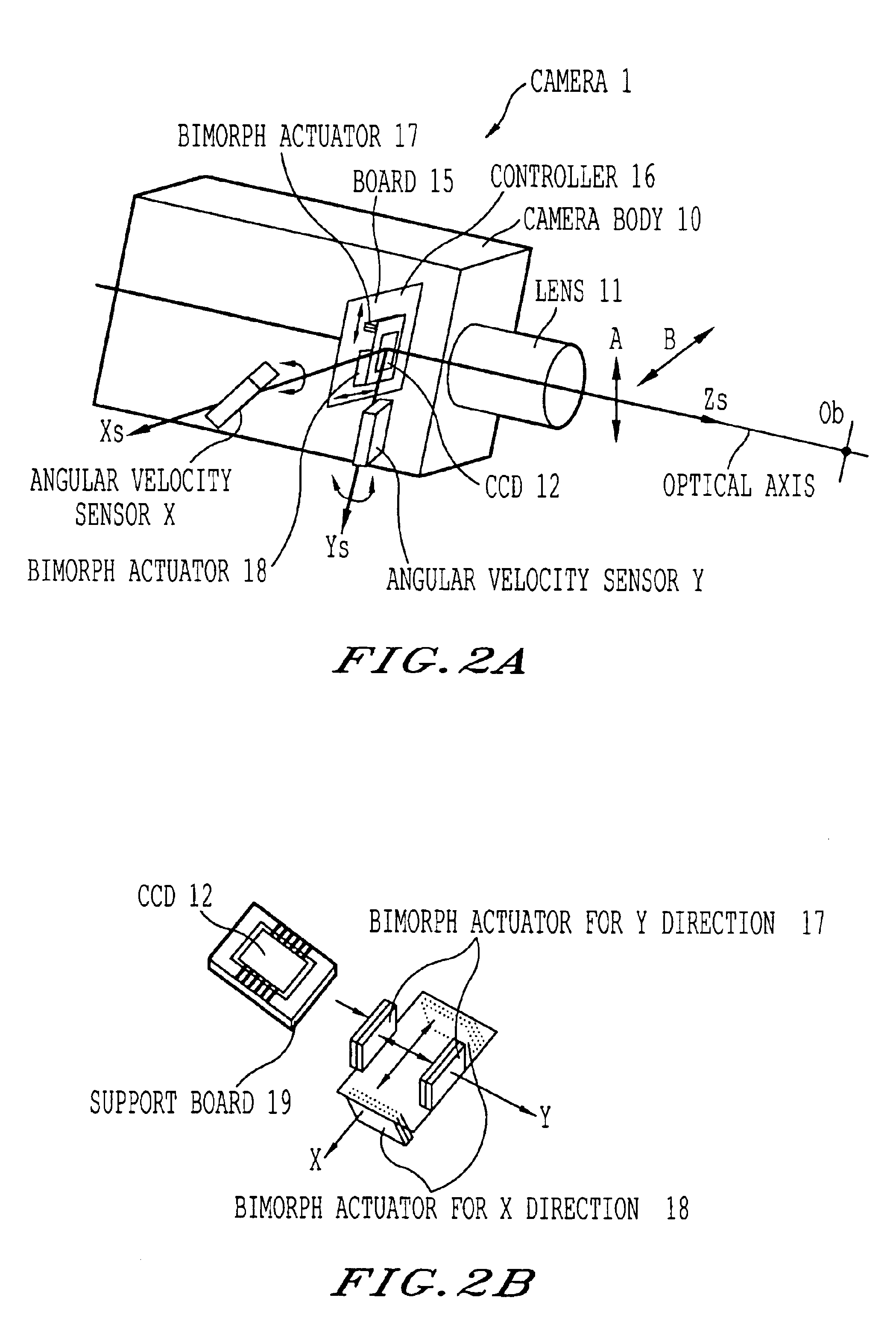
[0092]The support board 19 is equipped with a pair of Bimorph actuators 17 for the Y direction and a pair of Bimorph actuators 18 for the X direction, as in the

[0093]Now referring to FIG. 11, the pair of acceleration sensors Z1, Z2 detects the camera shaking in the pitching direction according to the camera shaking.

[0094]FIG. 11 shows a drawing of a cross-section of the YZ plane.

[0095]When the camera body 10 is inclined at an angle θ toward Ob in the YZ plane as a result of up-and-down motion of the camera, the output of the acceleration sensor Z1 is acceleration A1 at a distance L1′ from Ob, and the output of the acceleration sensor Z2 is acceleration A2 at a distance L2 from Ob. The accelerations A1 and A2 are described in the following equations (1), (2). In the equations (1), (2), ω is rotation angular velocity, and t is time. A1=L1′⁡(ⅆωⅆt)(1)A2=L2′⁡(ⅆωⅆt)(2)

When equation (1) is subtracted from equation (2). A2-A1=(ⅆωⅆt)⁢(L2′-L1′)(3)

[0096]The distance (L2′−L1′) equals the distan...


PUM


Abstract

A detecting system for detecting a deviation of a camera from shaking has at least two shaking detectors and one correcting device. The first shaking detector detects a camera shaking corresponding to one axis of a camera coordinate system. The second shaking detector detects a camera shaking corresponding to another axis of the camera coordinate system. The correcting device only adjusts a device corresponding to the first shaking detector in an optical system when a maximum or minimum value is detected on the output signal from the second shaking detector.

Description

BACKGROUND OF THE INVENTION[0001]1. Field of the Invention[0002]This invention is generally related to an apparatus and a method for correction based upon detecting a deviation from a proper position of a camera, and more particularly is related to an apparatus for correcting deviation from the proper camera position caused by shaking, such as hand shaking.[0003]2. Background of the Invention[0004]Digital video cameras and digital still cameras, are kinds of cameras which are well known. When those kinds of cameras shoot a subject, the optical system of the camera brings rays of light corresponding to the subject to a focus at an image pickup device and changes the information of the light into the electric signals.[0005]When the camera shaking occurs in the digital video camera, taken pictures slightly oscillate according to the camera shaking. Therefore, it is hard to watch the reproduced pictures of the digital video camera.[0006]In the digital still camera, the camera can not re...

Claims


Application Information

Patent Timeline
Patent Type & Authority Patents(United States)
IPC IPC(8): G03B39/00G03B17/00H04N5/228H04N5/232
CPCH04N5/23248H04N5/23283H04N5/23287H04N23/686H04N23/68H04N23/687
Inventor SATO, YASUHIROKITAGUCHI, TAKASHI
Owner RICOH KK
Why Eureka
Try Eureka