Image processing method and apparatus

a processing method and image technology, applied in the field of image processing methods and apparatuses, can solve the problems of blurring, sudden loss of distinction, image blurring about moving objects, etc., and achieve the effect of enhancing edges

Inactive Publication Date: 2005-08-16
KK TOSHIBA
View PDF3 Cites 19 Cited by
  • Summary
  • Abstract
  • Description
  • Claims
  • Application Information

AI Technical Summary

Benefits of technology

[0014]The invention may provide an image processing method including: discriminating between a still picture area and a motion picture area in an input image; enhancing edges with a quantity of edge enhancement larger in the motion picture area than in the still picture area; and outputting the input image having the enhanced edges.

Problems solved by technology

Thus, imaging blurring arises about a moving object.
Such blurring gives a sense of discomfort to an observer.
In this case, as soon as the object moves, imaging blurring occurs so that a sense of distinction is lost suddenly.
Thus, the sense of discomfort is great at the start of motion.
Particularly, in the case of an LCD, blurring of the moving object occurs also due to its insufficient speed of response.
On the other hand, when the object is moving, there occurs together the reduction of sharpness due to imaging blurring and the reduction of sharpness due to the fact that edge enhancement processing is not performed satisfactorily due to the reduction of sharpness caused by imaging blurring.
That is, in the related art, adequate researches have not been made as to how to perform edge enhancement processing to display a more natural picture image.

Method used


Image

  • Image processing method and apparatus
  • Image processing method and apparatus
  • Image processing method and apparatus

Examples


first embodiment

(First Embodiment)

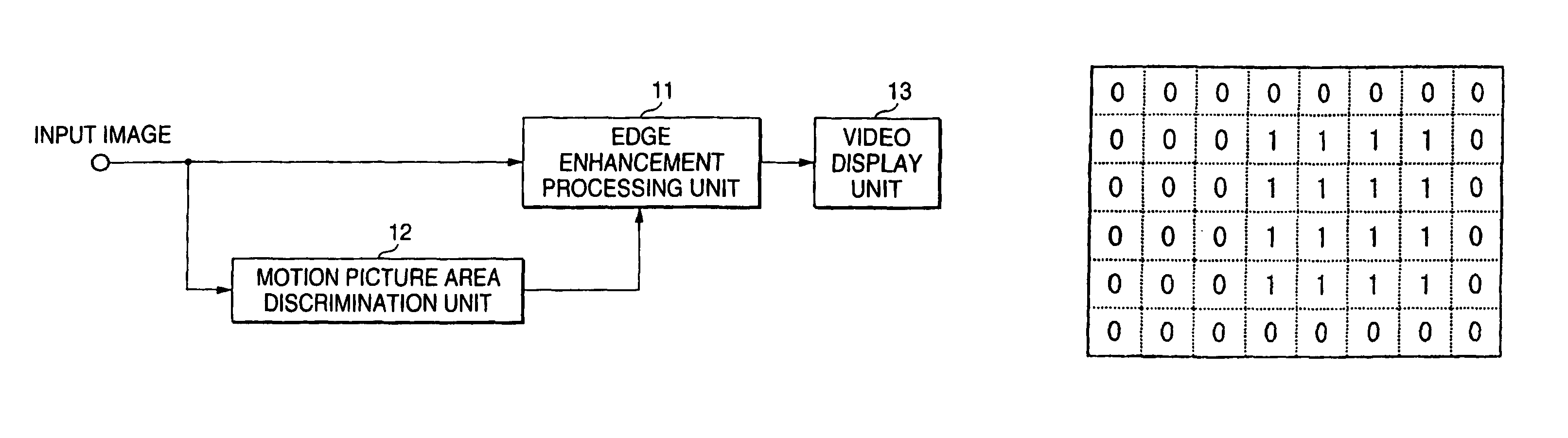
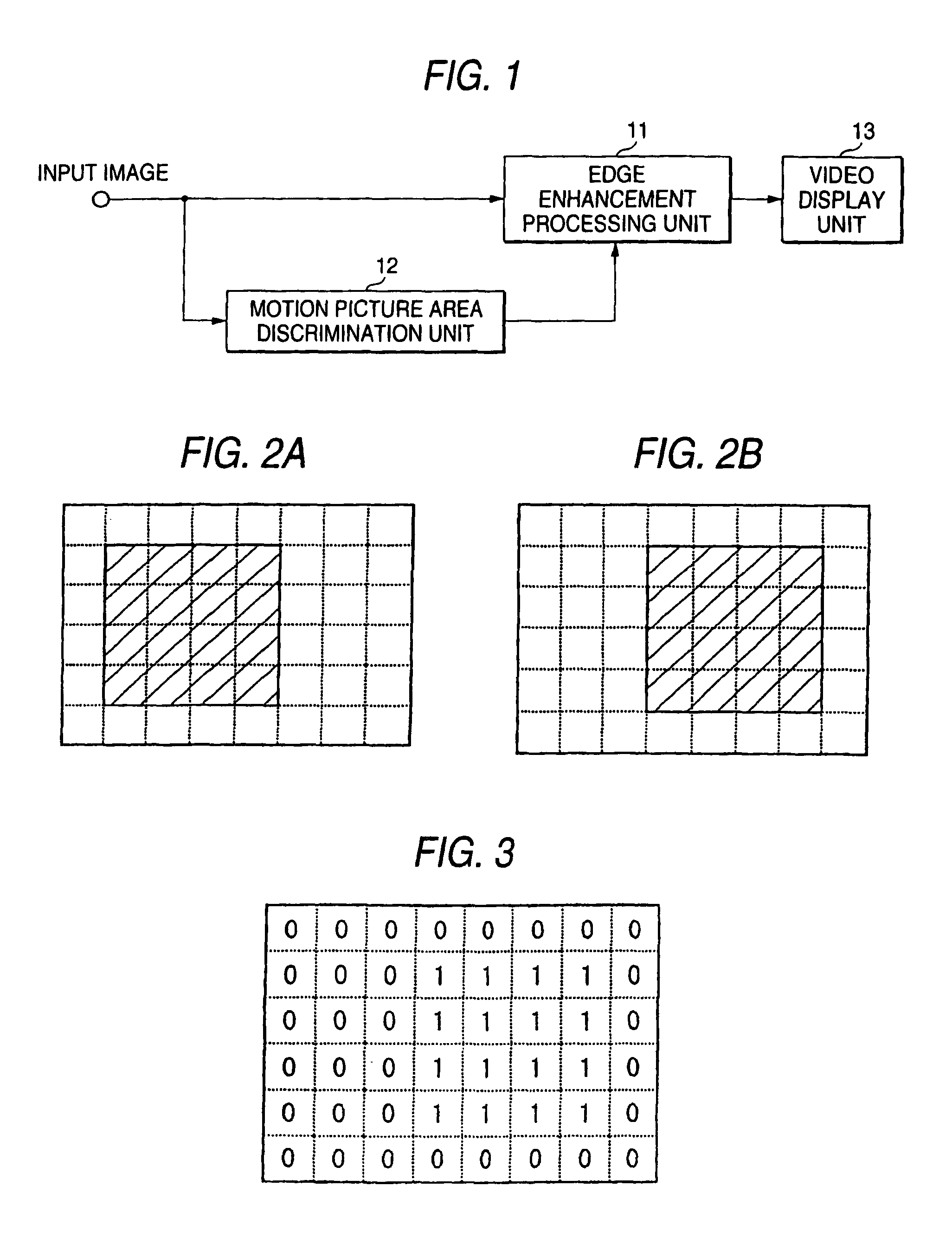
[0031]FIG. 1 shows a block diagram according to the first embodiment.

[0032]An input image is supplied to an edge enhancement processing unit 11 and a motion picture area discrimination unit 12.

[0033]The motion picture area discrimination unit 12 discriminates between motion picture areas and still picture areas, and supplies position information of the motion picture areas to the edge enhancement processing unit 11 as motion picture area information.

[0034]In the edge enhancement processing unit 11, edge enhancement processing is performed with different degrees of edge enhancement between the still picture areas and the motion picture areas of the input image on the basis of the motion picture area information.

[0035]After that, the image subjected to the edge enhancement processing is supplied to a video display unit 13 so as to be presented to an observer.

[0036]Next, the operation of each unit will be described.

[0037]The motion picture area discrimination unit 12 ...

second embodiment

(Second Embodiment)

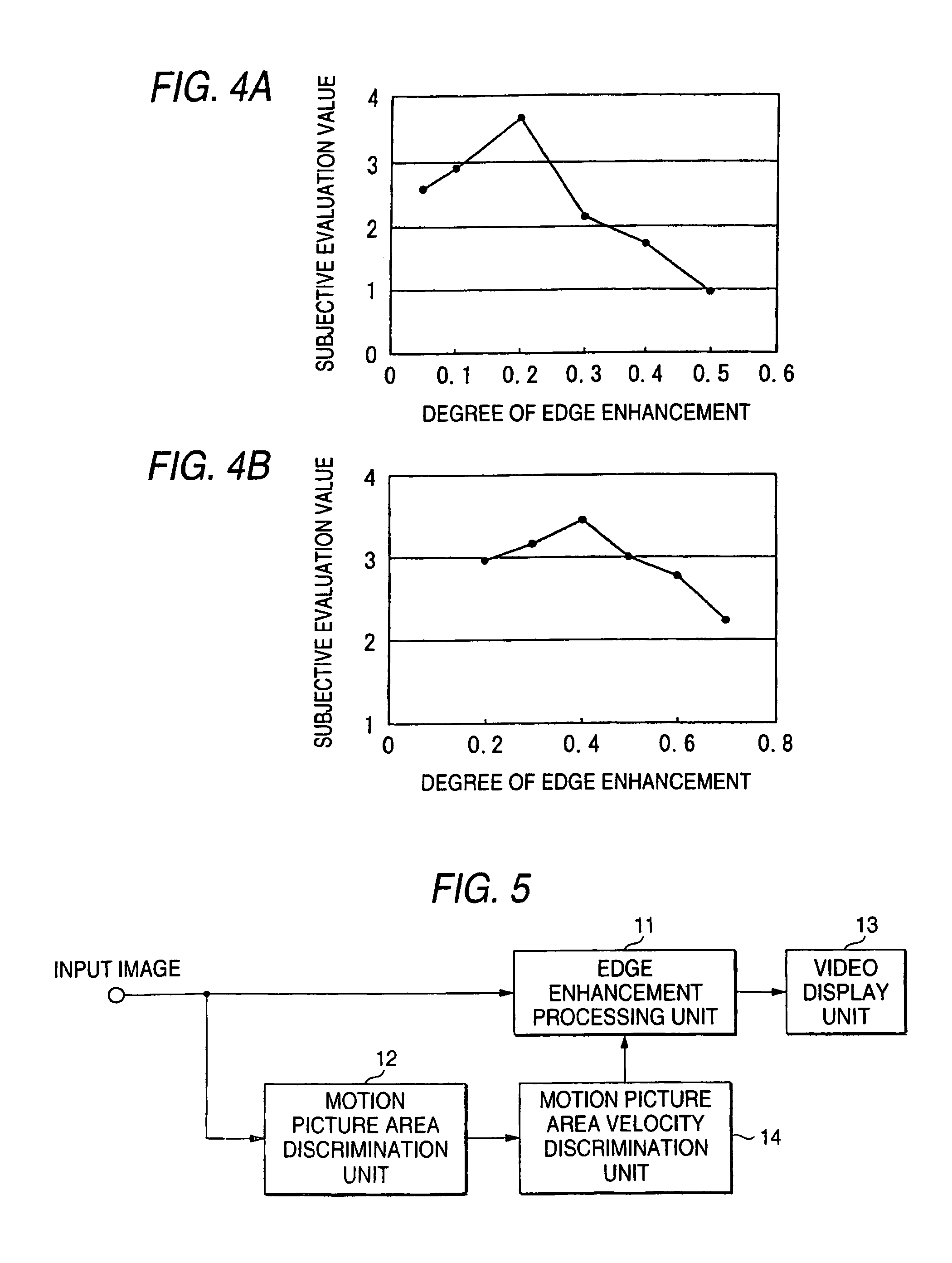
[0058]FIG. 5 shows a block diagram of the second embodiment related to a video display method according to the invention. Incidentally, in FIG. 5, constituent units the same as those in FIG. 1 are denoted by the same reference numerals correspondingly, and duplicated description will be omitted.

[0059]The fundamental configuration is similar to that of the first embodiment, except that a motion picture area velocity discrimination unit 14 for discriminating a motion velocity for each moving object divided by the motion picture area discrimination unit 12 is added in this embodiment.

[0060]The positions and velocities of the motion picture areas obtained by the motion picture area velocity discrimination unit 14 are supplied to the edge enhancement processing unit 11 as motion picture area velocity information.

[0061]In the edge enhancement processing unit 11, edge enhancement processing in accordance with the motion velocities in the still picture areas and the motio...

third embodiment

(Third Embodiment)

[0074]Also in this embodiment, the fundamental configuration is similar to that of the first embodiment. However, this embodiment is characterized in that the degree of edge enhancement for each pixel is determined in accordance with the size of a difference value of gradation for each pixel between an input image and an input image delayed for one frame period.

[0075]FIG. 7 shows a block diagram of this embodiment. Here, parts the same as those in the previous embodiments are denoted by the same reference numerals correspondingly, and detailed description thereof will be omitted.

[0076]An input image is supplied to a frame memory unit 15 and an interframe difference discrimination unit 16.

[0077]In the frame memory unit 15, an image of one frame is held, delayed for one frame period, and supplied to the interframe difference discrimination unit 16.

[0078]The interframe difference discrimination unit 16 obtains an absolute difference value of gradation for each pixel b...


PUM


Abstract

An image processing method includes: discriminating between a still picture area and a motion picture area in an input image; enhancing edges with a quantity of edge enhancement larger in the motion picture area than in the still picture area; and outputting the input image having the enhanced edges. The output having the enhanced edges is displayed on a display unit.

Description

[0001]The present disclosure relates to the subject matter contained in Japanese Patent Application No. 2002-236431 filed Aug. 14, 2002, which is incorporated herein by reference in its entirety.BACKGROUND OF THE INVENTION[0002]1. Field of the Invention[0003]The present invention relates to an image processing method and apparatus.[0004]2. Background Art[0005]A typical imaging system accumulates, for example, images for one frame period and outputs the images as a one-frame picture. Thus, imaging blurring arises about a moving object.[0006]That is, in an image, an edge of an object shows discontinuity in gradation. Assume that the object moves within the image. Even when the edge position moves, a distinct and clear image can be displayed if the edge is recorded and displayed as clear discontinuity in gradation.[0007]In a typical imaging system, however, the motion of the object for one frame period is accumulated. Thus, the discontinuity in gradation expressing the edge is not reco...

Claims


Application Information

Patent Timeline
Patent Type & Authority Patents(United States)
IPC IPC(8): G03B19/18G03B19/00G09G3/20H04N5/208G09G5/00G09G5/36
CPCG03B19/18
Inventor BABA, MASAHIROITOH, GOH
Owner KK TOSHIBA
Why Eureka
Try Eureka