Apparatus and methods for container inspection

Active Publication Date: 2008-11-27
APPLIED VISION
View PDF19 Cites 18 Cited by
  • Summary
  • Abstract
  • Description
  • Claims
  • Application Information

AI Technical Summary

Benefits of technology

[0016]These and other advantages and novel features of the present invention, as well as details of ill

Problems solved by technology

Furthermore, the rim coating on the bottom surface rim of a container is typically invisible under normal lighting conditions but is sensitive to ultraviolet light.
Such manu

Method used


Image

  • Apparatus and methods for container inspection
  • Apparatus and methods for container inspection
  • Apparatus and methods for container inspection

Examples


first embodiment

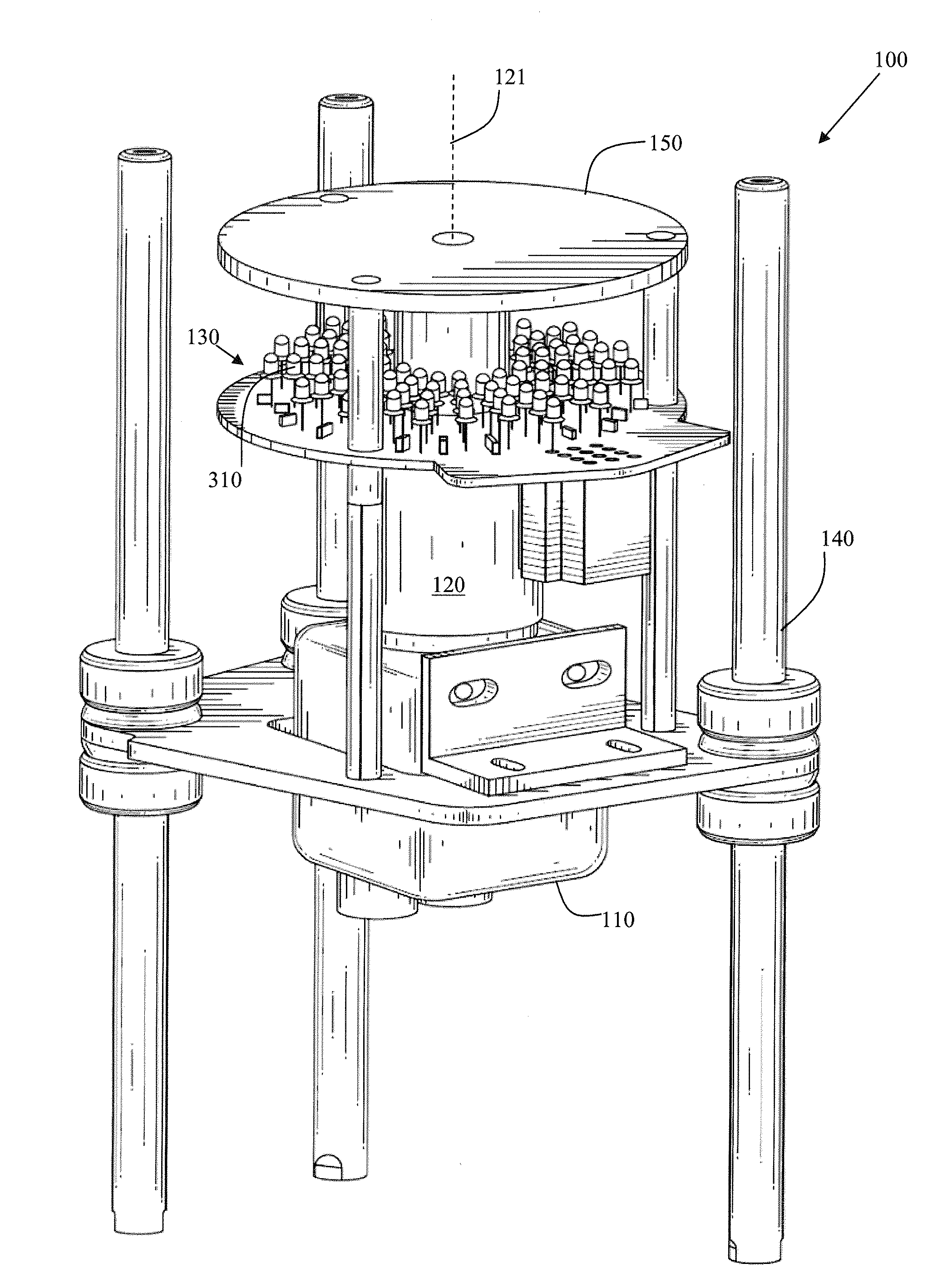
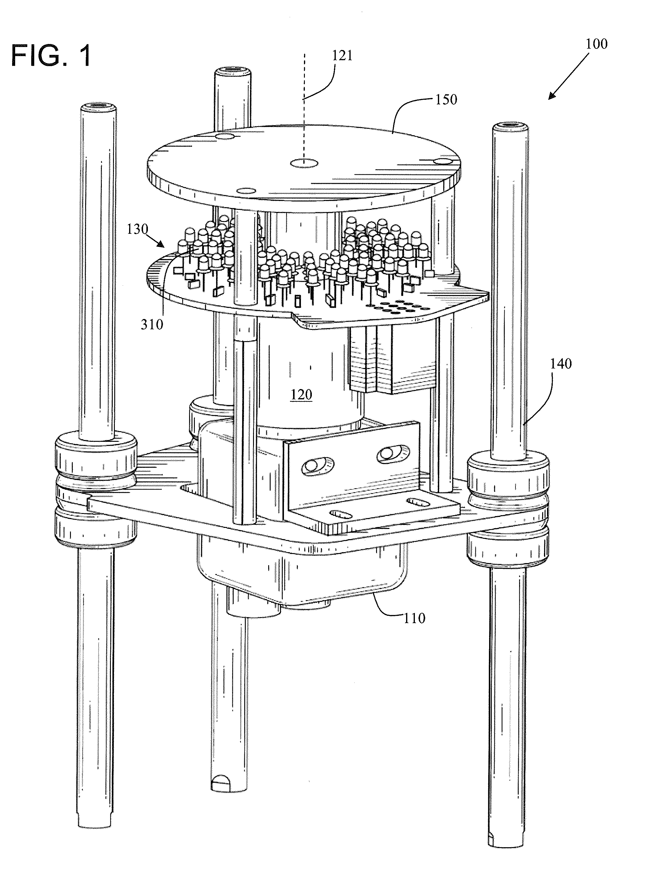
[0032]FIG. 1 is an illustration of an apparatus 100 for imaging a surface of each of a plurality of embossed metal containers, one at a time, as each container passes by the apparatus 100 on a metal container production line. The apparatus 100 includes a color camera 110 having an optical aperture, and a lens 120 having a central optical axis 121 and a capture angle. The lens 120 is operationally attached to the color camera 110 and is adapted to provide light to the optical aperture of the color camera 110. In accordance with an embodiment of the present invention, the capture angle of the lens 120 is about sixty-eight degrees. Other capture angles are possible as well. The camera 110 may comprise a digital color camera having an array of charged-coupled devices (CCDs), for example. Such digital cameras are well-known in the art. The lens 120 may include a “pin-hole” lens which is also well-known in the art.

[0033]The apparatus 100 also includes a source of illumination 130. The sou...

second embodiment

[0056]FIG. 7 is an illustration of an apparatus 700 for imaging a surface of each of a plurality of embossed metal containers, one at a time, as each container passes by the apparatus 700 on a metal container production line. The apparatus 700 includes a light source 710 (e.g., a substantially point light source such as a light-emitting diode or a light bulb). The apparatus 700 also includes a collimating lens 720 positioned to be illuminated on a first side by the light source and to output substantially parallel rays of light from a second side in response to the illumination.

[0057]The apparatus 700 further includes a beam-splitting mirror 730 positioned to first reflect the parallel rays of light received from the collimating lens 720. The apparatus includes a focusing lens 740 positioned to receive and focus the first reflected parallel rays of light forward to a focal point 750 and toward a substantially concave surface 760 of a metal container. The concave surface 760 of the m...


PUM


Abstract

Apparatus, systems, and methods to recognize features on bottom surfaces of containers on a container production line, detect defects in the containers, and correlate the defects to specific production equipment of the container production line, based in part on the recognized features. The system includes imaging apparatus, programmable processing devices, and controllers. The methods include imaging techniques and estimation techniques.

Description

TECHNICAL FIELD[0001]Certain embodiments of the present invention relate to inspection systems. More particularly, certain embodiments of the present invention relate to apparatus, systems, and methods for correlating detected defects in containers to specific production equipment on a container production line.BACKGROUND[0002]Metal containers are produced on metal container production lines at high speeds of, for example, 2000 containers per minute. The bodies of metal containers such as, for example, aluminum beverage cans, are formed by machines called “bodymakers”. A bodymaker machine may perform, for example, stretching of the aluminum to create the straight sides and bottom of the metal container. At a typical metal container manufacturing plant, multiple bodymakers (e.g., 20) may feed into a single production line. The containers are processed as they move down the production line.[0003]One process step is to spray-coat the inside of the containers. For example, there may typ...

Claims


Application Information

Patent Timeline
IPC IPC(8): G01N21/00
CPCG01N21/9036G01N21/9045G01N21/909G01N2021/8854
Inventor SONES, RICHARD A.SEBENY, CARL E.BAIRD, BRIAN M.KRESS, MICHAEL A.KRESS, MICHAEL L.
Owner APPLIED VISION
Why Eureka
Try Eureka