Bicycle wheel rim

a technology of bicycle wheels and rims, which is applied in the direction of rims, vehicle components, transportation and packaging, etc., can solve the problems of not having a strait beam incorporated between the inner and outer bridge structures to strengthen the rim, and the known prior art does not show a tire bead retention system spanning several tire configurations, so as to improve the tire bead retention system and strengthen the rim

Inactive Publication Date: 2009-05-07
WILDERNESS TRAIL BIKES LICENSING
View PDF13 Cites 19 Cited by
  • Summary
  • Abstract
  • Description
  • Claims
  • Application Information

AI Technical Summary

Benefits of technology

[0011]The present invention is a bicycle wheel rim with an improved tire bead retention system. The inventive rim also includes a novel vertical beam disposed between inner bridge and outer bridge structures to strengthen the rim.
[0014]The first bead seat and the second bead seat are essentially parallel to the inner bridge. The proximal portion of the first bead seat and the second bead seat each exhibit a stasis bump projecting outwardly near the lateral wall and descending to the radial plane of the bead seat. The stasis bumps serve to prevent tire bead slippage inwardly on the rim.
[0016]The outer wall of each of the second rim wall and the first rim wall has a rim hook bulge located at approximately opposite the junction of the bead seat and the rim wall. The rim hook bulge adds significant strength to the tire bead hook.
[0017]Disposed between and in communication with the outer bridge and the inner bridge, and perpendicular to the radial planes of the inner and outer bridges, is a vertical beam which extends the entire circumference of the rim. The vertical beam is a ring which, when viewed in cross section, is substantially straight, with a thickness at its base (where it connects to the inner bridge) being slightly greater than its thickness where it intersects the outer bridge. The vertical beam lends increased strength and rigidity to the bicycle wheel rim.
[0018]It is thus an object of the present invention to create a stronger and more rigid bicycle wheel rim through the use of a vertical beam disposed between outer and inner bridges of the rim.

Problems solved by technology

Specifically, none of the known prior art shows a tire bead retention system spanning several tire configurations, nor a strait beam incorporated between the inner and outer bridge structures to strengthen the rim.

Method used


Image

  • Bicycle wheel rim
  • Bicycle wheel rim
  • Bicycle wheel rim

Examples


Embodiment Construction

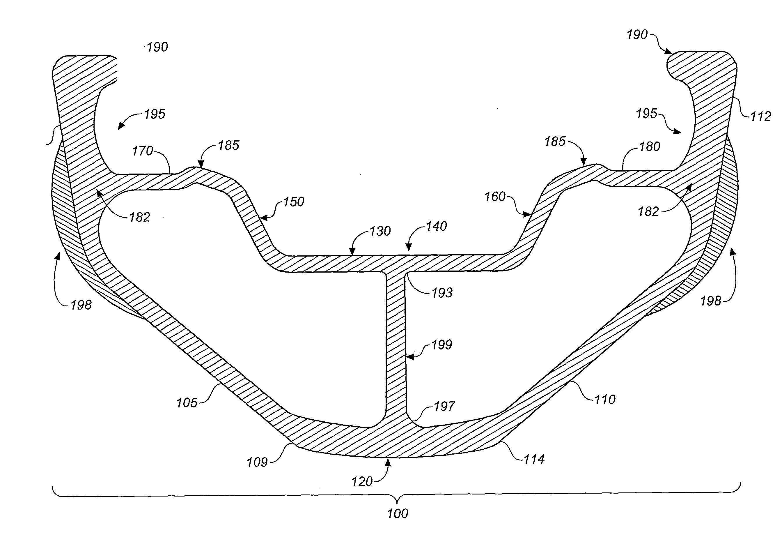
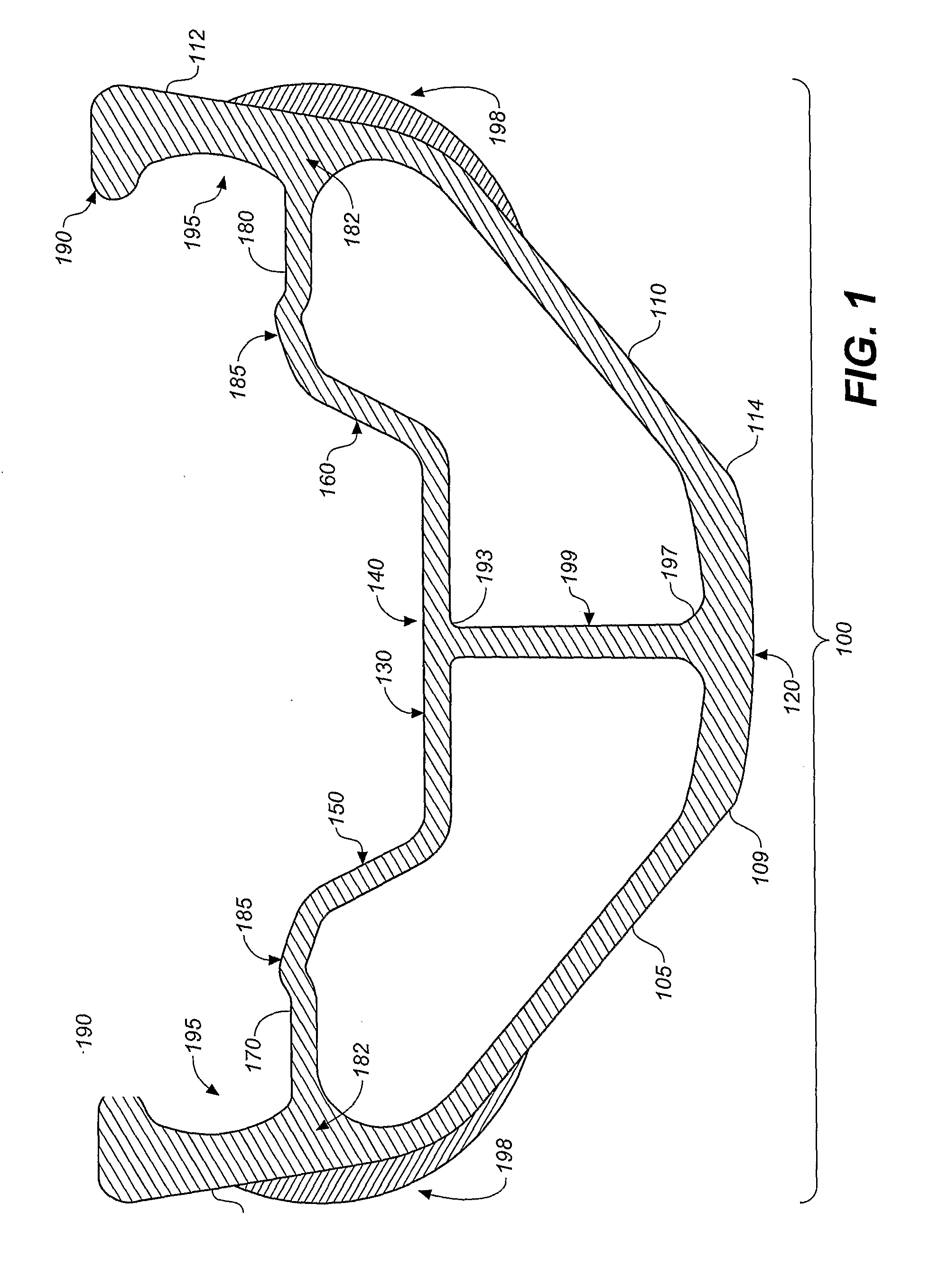
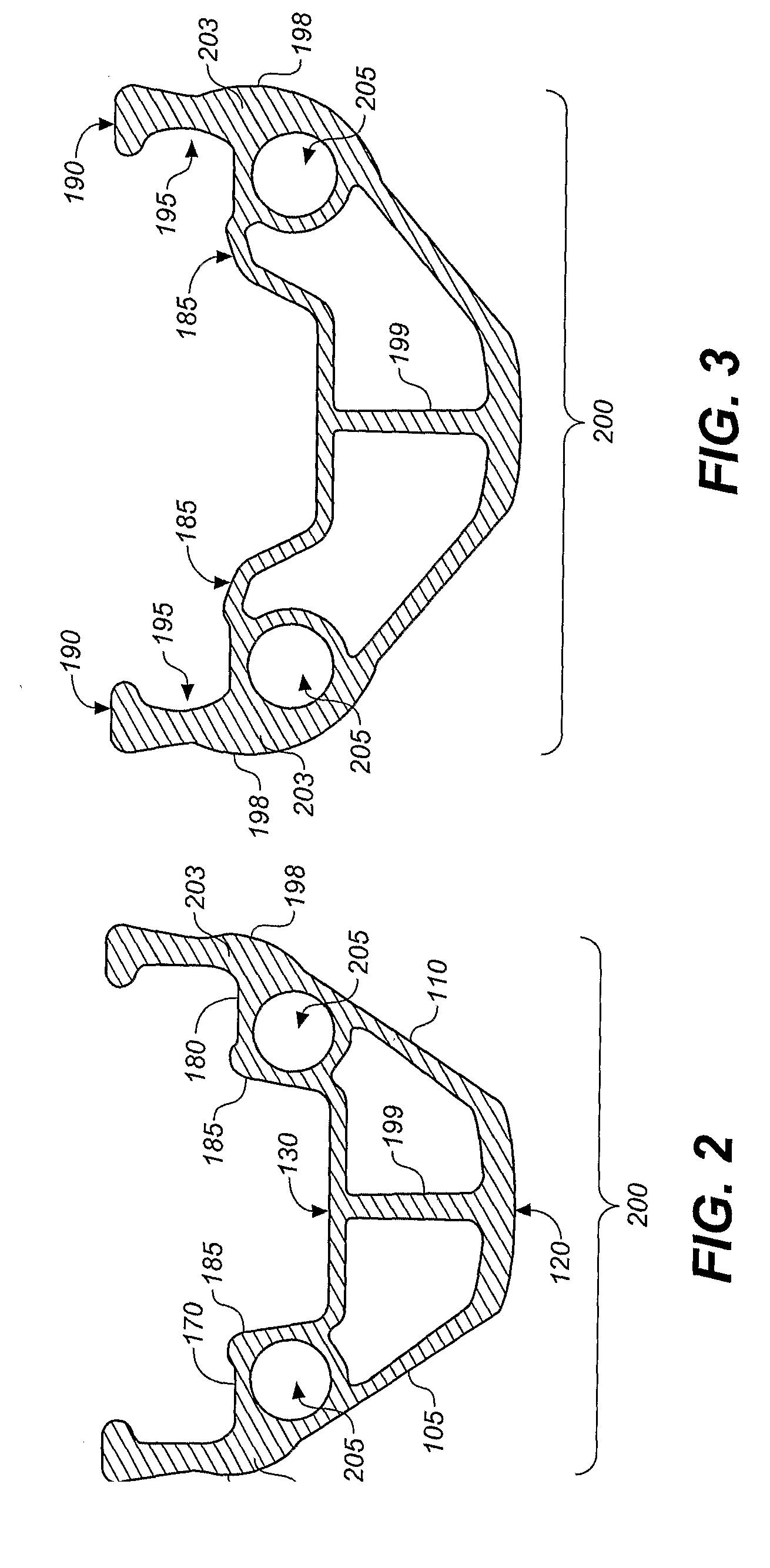
[0052]Referring to FIGS. 1 through 3, wherein like reference numerals refer to like components in the various views, there is illustrated therein a new and improved hollow bicycle wheel rim, generally denominated 100 herein.

[0053]FIG. 1 illustrates a first preferred embodiment of the improved bicycle wheel rim 100, comprising an angled annular ring forming a first rim wall 105, and an angled annular ring forming a second rim wall 110. The first rim wall includes a distal portion 107 and a proximal portion 109. The second rim wall also includes a distal portion 112 and a proximal portion 114. The first and second rim walls are joined at their respective proximal inner edges by an annular inner bridge 120.

[0054]An annular outer bridge 130 is disposed at approximately the midpoint of the second rim wall and the first rim wall and is generally parallel to the inner bridge 120. The outer bridge 130 has a central well 140 defined by a first lateral wall 150 and a second lateral wall 160, ...


PUM


Abstract

A bicycle wheel rim having rim walls joined at their proximal ends by an inner annular bridge, an annular outer bridge disposed at the approximate midpoint of the rim walls, and a vertical beam disposed between the outer and inner bridges.

Description

BACKGROUND OF THE INVENTION[0001]1. Technical Field[0002]The present invention relates generally to bicycle wheel rims, more particularly to a bicycle wheel rim having an improved tire bead retention system, and further having a novel vertical beam disposed between inner and outer bridge structures which strengthens the rim.[0003]2. Background Art[0004]Bicycle wheels are well known in the art, generally having two spaced-apart annular tire retaining walls connected by an annular spoke mounting wall disposed between the radial inner walls of the two annular tire retaining walls. As materials technology has matured, several improvements have been introduced into wheel rim designs. In particular, metal alloys and composition materials, such as carbon fiber, have been increasingly employed to reduce weight and to add strength and stability.[0005]Different tire systems demand different shapes for the retention of such tires. High speeds, rough terrain, and heavier riders have further inc...

Claims


Application Information

Patent Timeline
Patent Type & Authority Applications(United States)
IPC IPC(8): B60B21/02
CPCB60B21/025B60B21/028B60B21/104B60B21/062B60B21/04
Inventor SLATE, MARKDEETZ, JOSHSEIDLER, PATRICK
Owner WILDERNESS TRAIL BIKES LICENSING
Why Eureka
Try Eureka