
Training sequence with a random delay for a radio communications system

Inactive Publication Date: 2005-08-16
INTEL CORP
View PDF12 Cites 111 Cited by
  • Summary
  • Abstract
  • Description
  • Claims
  • Application Information

AI Technical Summary

Problems solved by technology

If the request is received at the same time as the colliding request, it can be difficult to resolve the colliding requests at the base station.
However, accurate delay timing advance or delay assignments cannot be made by the base station until the range to each of the user terminals is known.
In addition, the BCH does not permit assignments to be made as it is the same for all user terminals that receive it.

Method used


Image

  • Training sequence with a random delay for a radio communications system
  • Training sequence with a random delay for a radio communications system
  • Training sequence with a random delay for a radio communications system

Examples


Embodiment Construction

Base Station Structure

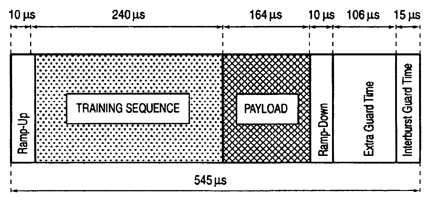
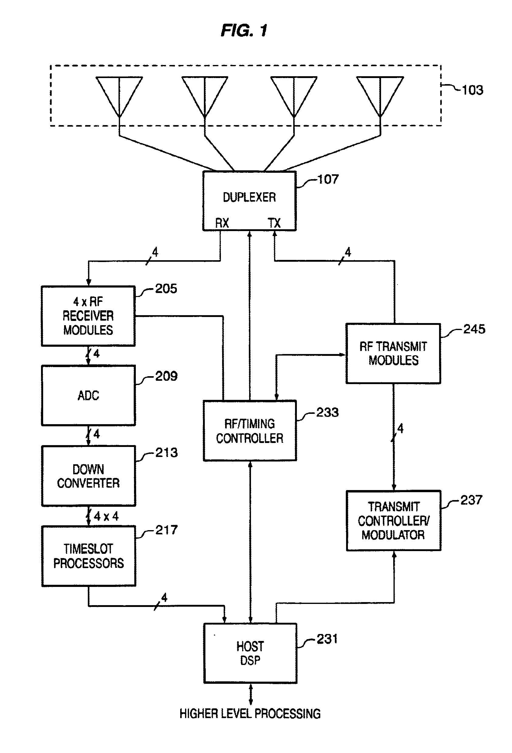
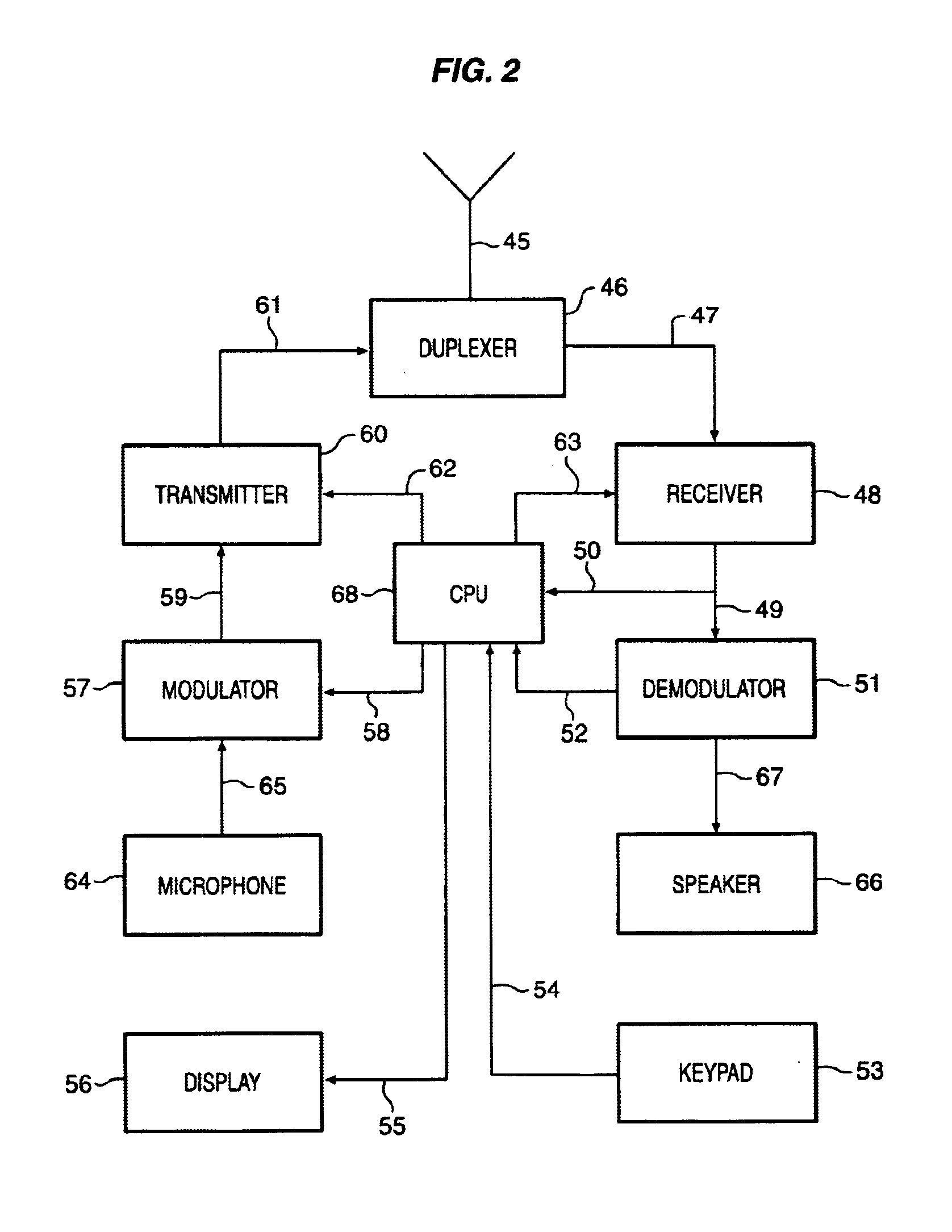
[0017]The present invention relates to wireless communication systems and may be a fixed-access or mobile-access wireless network using spatial division multiple access (SDMA) technology in combination with multiple access systems, such as time division multiple access (TDMA), frequency division multiple access (FDMA) and code division multiple access (CDMA). Multiple access can be combined with frequency division duplexing (FDD) or time division duplexing (TDD). FIG. 1 shows an example of a base station of a wireless communications system or network suitable for implementing the present invention. The system or network includes a number of subscriber stations, also referred to as remote terminals or user terminals, such as that shown in FIG. 2. The base station may be connected to a wide area network (WAN) through its host DSP 231 for providing any required data services and connections external to the immediate wireless system. To support spatial diversity, a...


PUM


Abstract

A method and apparatus are provided that allows a delay to be chosen to be applied to a user terminal. According to one aspect of the present invention, the invention includes receiving a downlink broadcast burst from a base station, determining timing for an uplink burst from the received broadcast burst, selecting an amount of delay for the uplink burst, and transmitting an uplink burst to the base station using the determined timing and the selected amount of delay.

Description

BACKGROUND OF THE INVENTION[0001]1. Field of the Invention[0002]The present invention applies to burst timing for radio communications systems and, in particular, to selecting from among different amounts of delay for use in sending a burst from one station to another.[0003]2. Description of the Prior Art[0004]Mobile radio communications systems such as cellular voice and data radio systems typically have several base stations in different locations available for use by mobile or fixed user terminals, such as cellular telephones or wireless web devices. Each base station typically is assigned a set of frequencies or channels to use for communications with the user terminals. The channels are different from those of neighboring base stations in order to avoid interference between neighboring base stations. As a result, the user terminals can easily distinguish the transmissions received from one base station from the signals received from another. In addition, each base station can a...

Claims


Application Information

Patent Timeline
IPC IPC(8): H04J3/06H04J13/00H04L7/04
CPCH04L7/041H04W56/0045H04J3/0682H04L7/042
Inventor DOGAN, MITHAT C.
Owner INTEL CORP
Learn More