Gray code counter

a counter and gray code technology, applied in exclusive-or-circuits, instruments, pulse techniques, etc., can solve the problems of increasing the cost of manufacturing such circuitry, reducing the resolution of the fpa chip, and logical complexity of prior art gray code binary counters

Active Publication Date: 2005-08-16
DRS NETWORK & IMAGING SYST
View PDF13 Cites 12 Cited by
  • Summary
  • Abstract
  • Description
  • Claims
  • Application Information

AI Technical Summary

Problems solved by technology

Prior art gray code binary counters, however, are logically complex and require substantial amounts of logic gating in their implementation.
If the counter occupies too much chip surface area, the portion of the FPA chip surface area allocated to an individual pixel would increase, thereby decreasing resolution for the FPA chip.
As chips become smaller and smaller to require finer geometries for manufacture of circuitry, the cost of manufacturing such circuitry increases.

Method used


Image

  • Gray code counter
  • Gray code counter
  • Gray code counter

Examples


Embodiment Construction

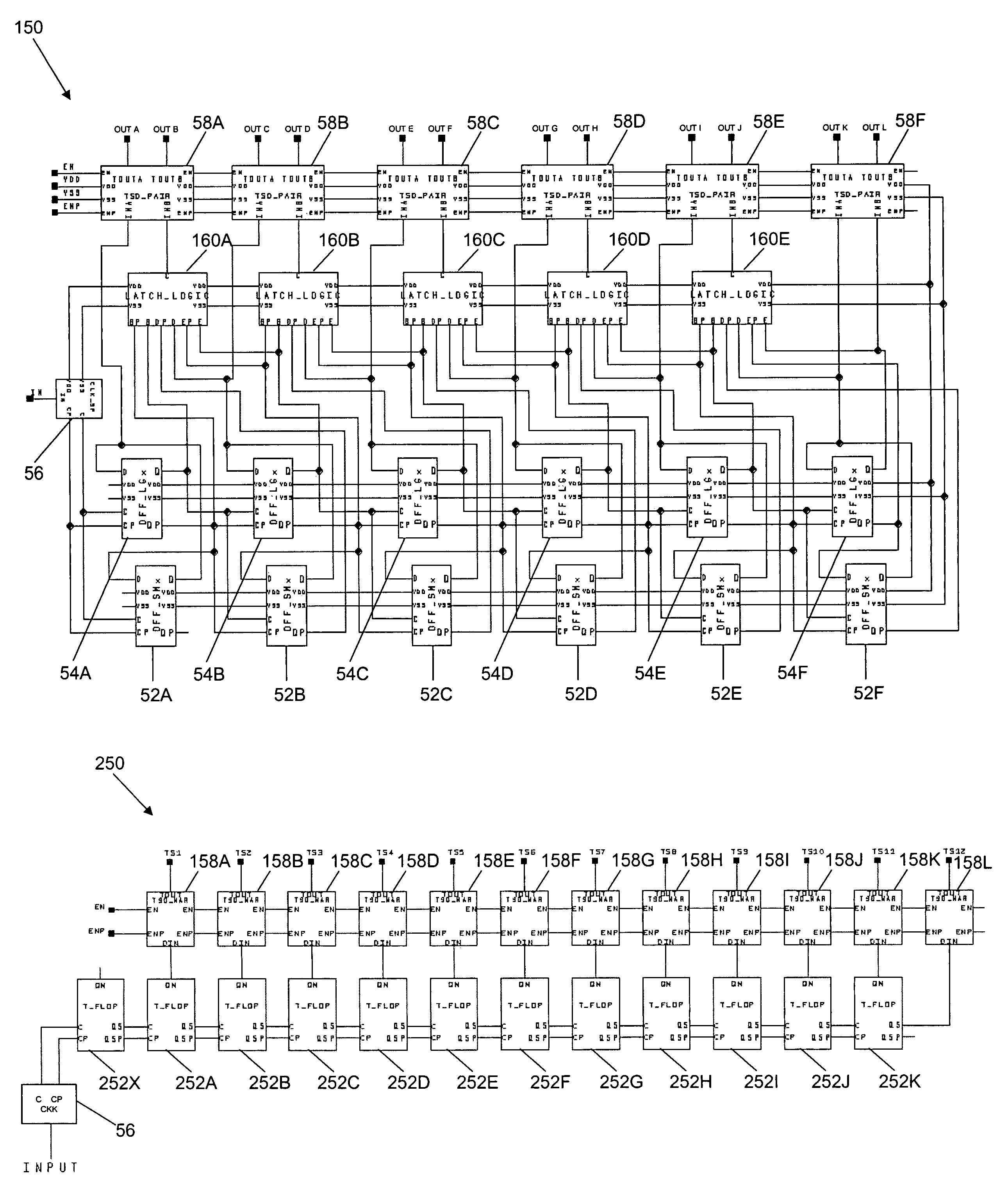
[0024]FIG. 3 illustrates a preferred gray code binary counter 50 having a minimum of gate logic in accordance with a first aspect the present invention. Referring to FIG. 3, the counter 50 is a N=12 bit counter having bit outputs readable at OUTA-OUTL. The counter 50 includes a chain of six pairs of D-type flip-flops 52 and 54. The flip-flop pairs 52, 54 are coupled to respective bit readers 58. A clock input device 56 is coupled to the first of the flip-flop pairs 52, 54 in the chain. In addition, the counter 50 includes five, three input exclusive-OR gate circuits 60 coupled to the bit readers 58 and the flip-flop pairs 52, 54.

[0025]Referring to FIG. 3, the clock device 56 includes a counter input IN, a clock output C, a complementary clock output CP and power supply nodes VSS and VDD. The exclusive-OR gate circuits 60 include inputs AINP, BIN, BINP, CIN and CINP, an output XOUT and power supply nodes VDD and VSS. The bit readers 58 include inputs INA and INB, outputs TOUTA and TO...


PUM


Abstract

A gray code is produced from a minimum of gate logic by making available and monitoring master outputs of master-slave latch pairs, where the latch pairs are arranged to form a cascading chain of toggle flip-flop stages. The least significant bit through one less than the most significant bit in the gray code is supplied by the master latch outputs and the most significant gray code bit is supplied by the slave latch output of the last toggle stage in the chain.

Description

CROSS REFERENCE TO RELATED APPLICATION[0001]This application claims the benefit of U.S. Provisional Application No. 60 / 529,375 filed Dec. 11, 2003, assigned to the assignee of this application and incorporated by reference herein.FIELD OF THE INVENTION[0002]The present invention relates generally to digital binary counters and, more particularly, to gray code digital binary counters having a minimum of logic circuitry.BACKGROUND OF THE INVENTION[0003]Digital binary counters are widely used in digital information processing systems. In general, a digital binary counter is formed from logic circuitry that includes N binary stages having respective bit outputs that change state in response to input pulses received at the counter. The states of the respective bit outputs change in accordance with a binary code that represents numerical values between 0 and 2N−1. Consequently, the digital binary counter can be used to generate a binary code that corresponds to a count of the number input...

Claims


Application Information

Patent Timeline
Patent Type & Authority Patents(United States)
IPC IPC(8): H03K19/21H03K23/00H03K19/20
CPCH03K19/215H03K23/005
Inventor HEIMBIGNER, GARY L.
Owner DRS NETWORK & IMAGING SYST
Why Eureka
Try Eureka