Method and system for collapsing a graphical representation of related elements

a technology of related elements and methods, applied in the field of data processing systems, can solve the problems of software developers eventually abandoning the model, graphical representation becomes more of a burden, and the development tools of conventional development tools are generally difficult to use for complex models, etc., and achieves the effect of simplifying the graphical representation of software code and facilitating the developer in graphically debugging and editing the associated elements

Inactive Publication Date: 2005-08-16
BORLAND
View PDF16 Cites 56 Cited by
  • Summary
  • Abstract
  • Description
  • Claims
  • Application Information

AI Technical Summary

Benefits of technology

[0012]Methods and systems consistent with the present invention provide an improved software development tool that simplifies a graphical representation of software code for a developer. The software development tool provides the developer with a more coherent, manageable, and abstract graphical view of the project model, and facilitates the developer in graphically debugging and editing the associated software code.

Problems solved by technology

Conventional development tools generally become difficult to use for complex models.
As multiple classes are defined and multiple relationships are extended, the graphical representation becomes more of a burden.
Faced with this problem, a software developer eventually will abandon the model as a system design development tool.
For example, a developer looking to debug an existing design or to revise an existing model of a software program to conform to new requirements (e.g., new inventory scheme for suppliers) may become frustrated when viewing a detailed, complex model, and decide to debug or edit the source code directly.
Conventional design tools that provide a graphical representation of code associated with modeling a business process or software project present an incoherent and unwieldy graphical view of the code when the respective model is complex.

Method used


Image

  • Method and system for collapsing a graphical representation of related elements
  • Method and system for collapsing a graphical representation of related elements
  • Method and system for collapsing a graphical representation of related elements

Examples


Embodiment Construction

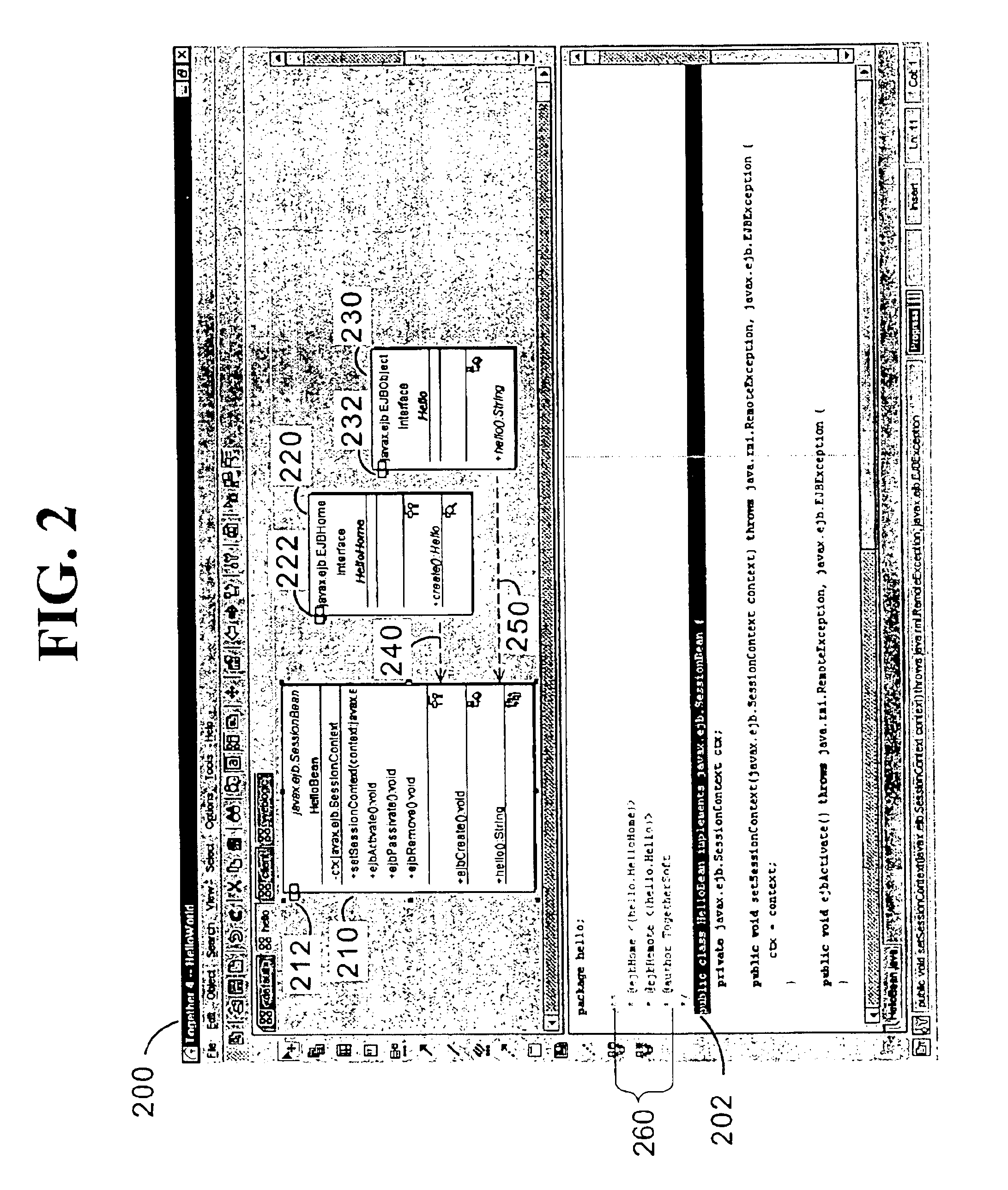
[0026]Methods and systems consistent with the present invention provide an improved software development tool which simplifies a graphical representation of software code to allow a developer to easily view a complex or unwieldy model of a software project without affecting the associated code. By collapsing the graphical notation for groups of related elements utilized in the software code, the software development tool simplifies the graphical view of the software code to allow a developer to focus on the important components and interactive flow of his / her software project and to assist the developer in debugging a design problem or in adding functionality to an already complex design.

Overview

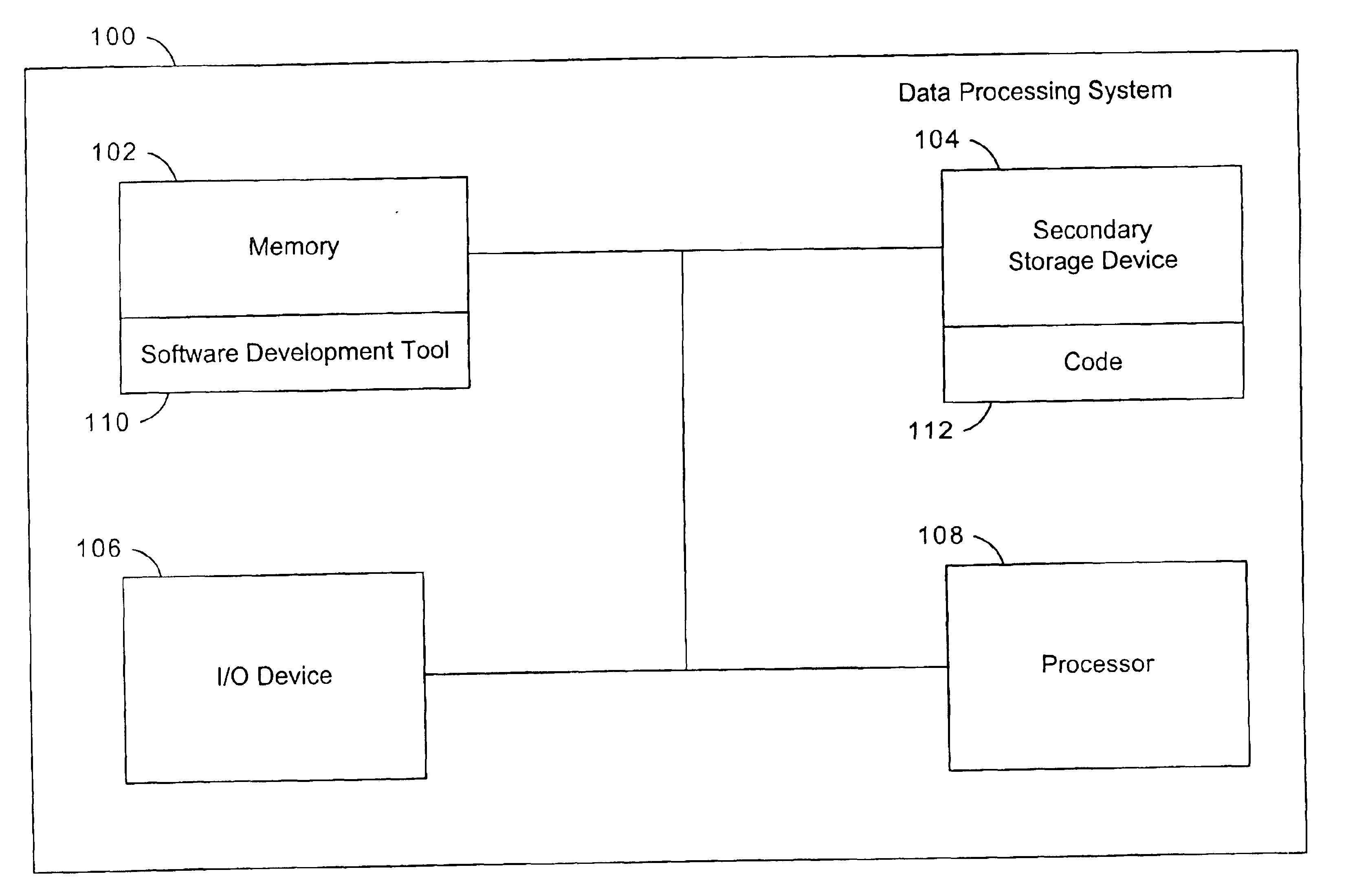
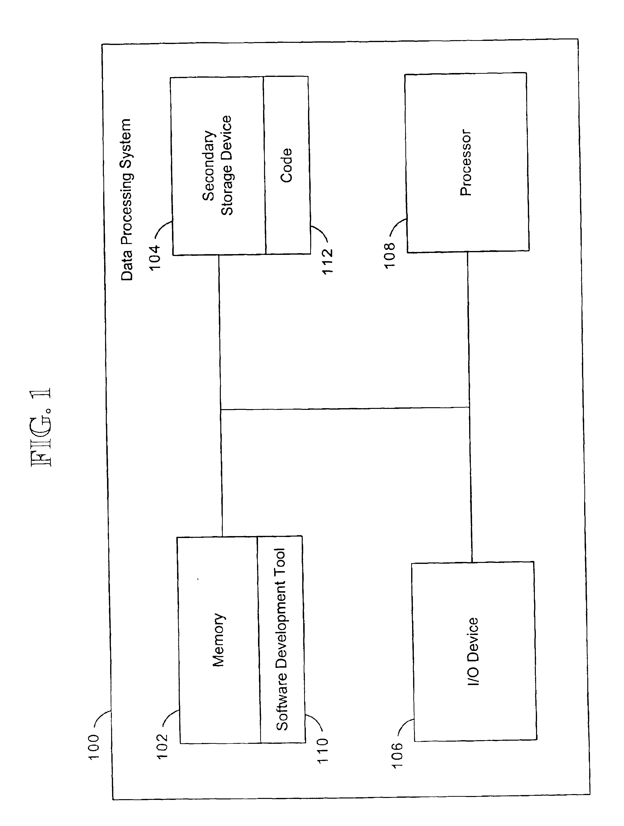
[0027]The improved software development tool is used in a data processing system for developing software code associated with a project. The software code includes a group of related elements. An element of the group of related elements may be a class, an object of a class, or an interface (...


PUM


Abstract

Methods and systems consistent with the present invention provide an improved software development tool that simplifies a graphical representation of software code for a developer. The software development tool provides the developer with a more coherent, manageable, and abstract graphical view of the project model, and facilitates the developer in graphically debugging and editing the associated software code. The improved software development tool detects a group of related elements in the code, and collapses a portion of the graphical representation of the code associated with the group of related elements.

Description

CROSS-REFERENCE TO RELATED APPLICATIONS[0001]The following identified U.S. patent applications are relied upon and are incorporated by reference in this application:[0002]U.S. Provisional Application No. 60 / 157,826, entitled “Visual Unified Modeling Language Development Tool,” filed on Oct. 5, 1999;[0003]U.S. Provisional Application No. 60 / 199,046, entitled “Software Development Tool,” filed on Apr. 21, 2000;[0004]U.S. patent application Ser. No. 09 / 680,063 entitled “Method And System For Developing Software,” and filed on the same date herewith;[0005]U.S. patent application Ser. No. 09 / 680,065, entitled “Method And System For Displaying Changes Of Source Code,” and filed on the same date herewith; and[0006]U.S. patent application Ser. No. 09 / 680,030, entitled “Method And System For Generating, Applying, And Defining A Pattern,” and filed on the same date herewith.FIELD OF THE INVENTION[0007]The present invention relates generally to data processing systems and, more particularly, t...

Claims


Application Information

Patent Timeline
Patent Type & Authority Patents(United States)
IPC IPC(8): G06F9/44
CPCG06F8/20G06F11/3664
Inventor COAD, PETERCHARISIUS, DIETRICHAPTUS, ALEXANDER
Owner BORLAND
Why Eureka
Try Eureka