
Multidirectional laser indicator

a laser indicator and multi-directional technology, applied in the direction of reference lines/planes/sectors, instruments, angle measurement, etc., can solve the problems of prone displacement of laser modules, time-consuming and difficult to properly implement, and 4/b> may also be unable to be joined at one time, etc., to achieve quick and easy adjustment

Inactive Publication Date: 2005-08-23
QUARTON
View PDF5 Cites 46 Cited by
  • Summary
  • Abstract
  • Description
  • Claims
  • Application Information

AI Technical Summary

Benefits of technology

[0007]It is an object of the present invention to provide a multidirectional laser indicator which allows for quick and easy adjustment of the direction of the laser module.
[0012]In accordance with another embodiment of the present invention, a stand is provided which includes a seat having a plurality of legs, and a rotary table having a plurality of legs, with the weight mechanism coupled to the rotary table, and the rotary table removably coupled to the seat so that altitude of the weight mechanism can be adjusted.

Problems solved by technology

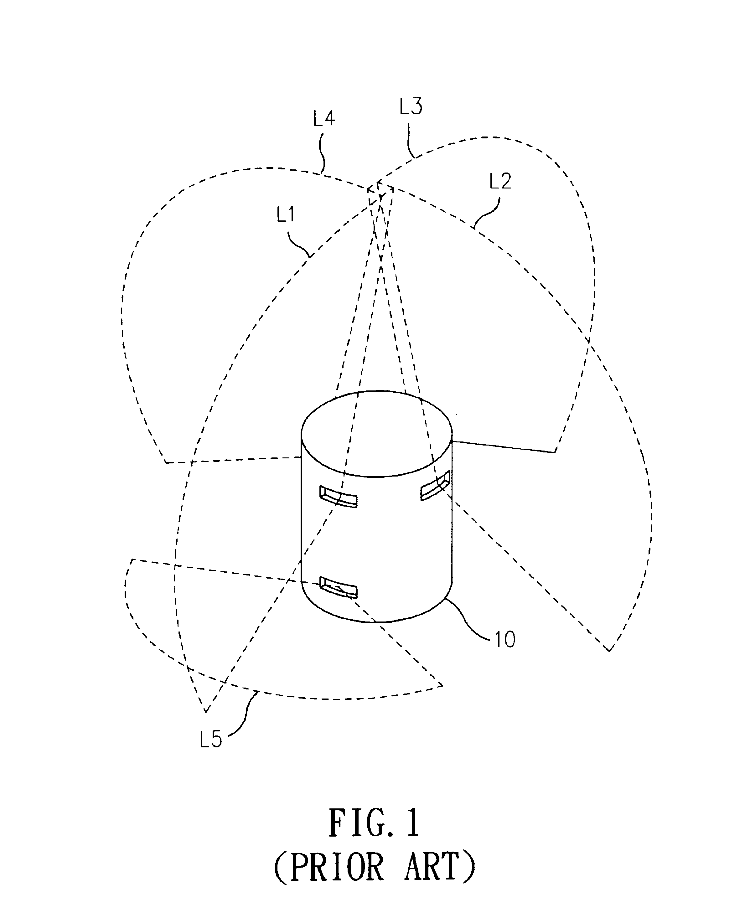
Unfortunately, since the laser module is prone to experience displacement after extended use, not only will the horizontal laser beam L5 be skewed (i.e., no longer horizontal), but the four vertical laser beams L1-L4 may also be unable to be joined at one point.
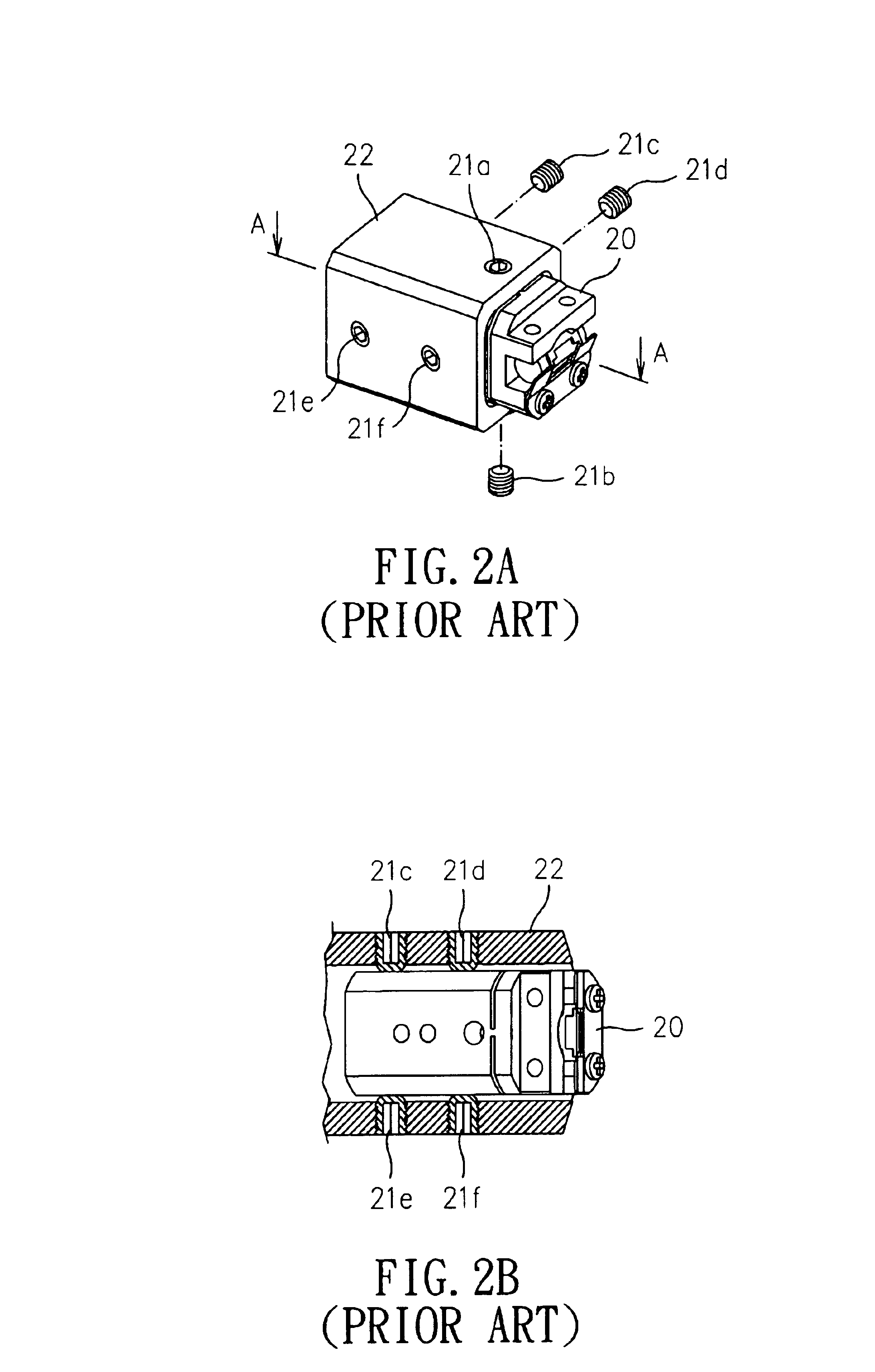
However, the major shortcoming of this six-point adjusting method is that it is very time-consuming and difficult to properly implement.
The adjustment can be very tedious, especially for an indicator that has four laser modules.
Furthermore, by providing six adjusting bolts in a laser module 20, the material cost is increased as well.

Method used


Image

  • Multidirectional laser indicator
  • Multidirectional laser indicator
  • Multidirectional laser indicator

Examples


Embodiment Construction

[0026]The following detailed description is of the best presently contemplated modes of carrying out the invention. This description is not to be taken in a limiting sense, but is made merely for the purpose of illustrating general principles of embodiments of the invention. The scope of the invention is best defined by the appended claims.

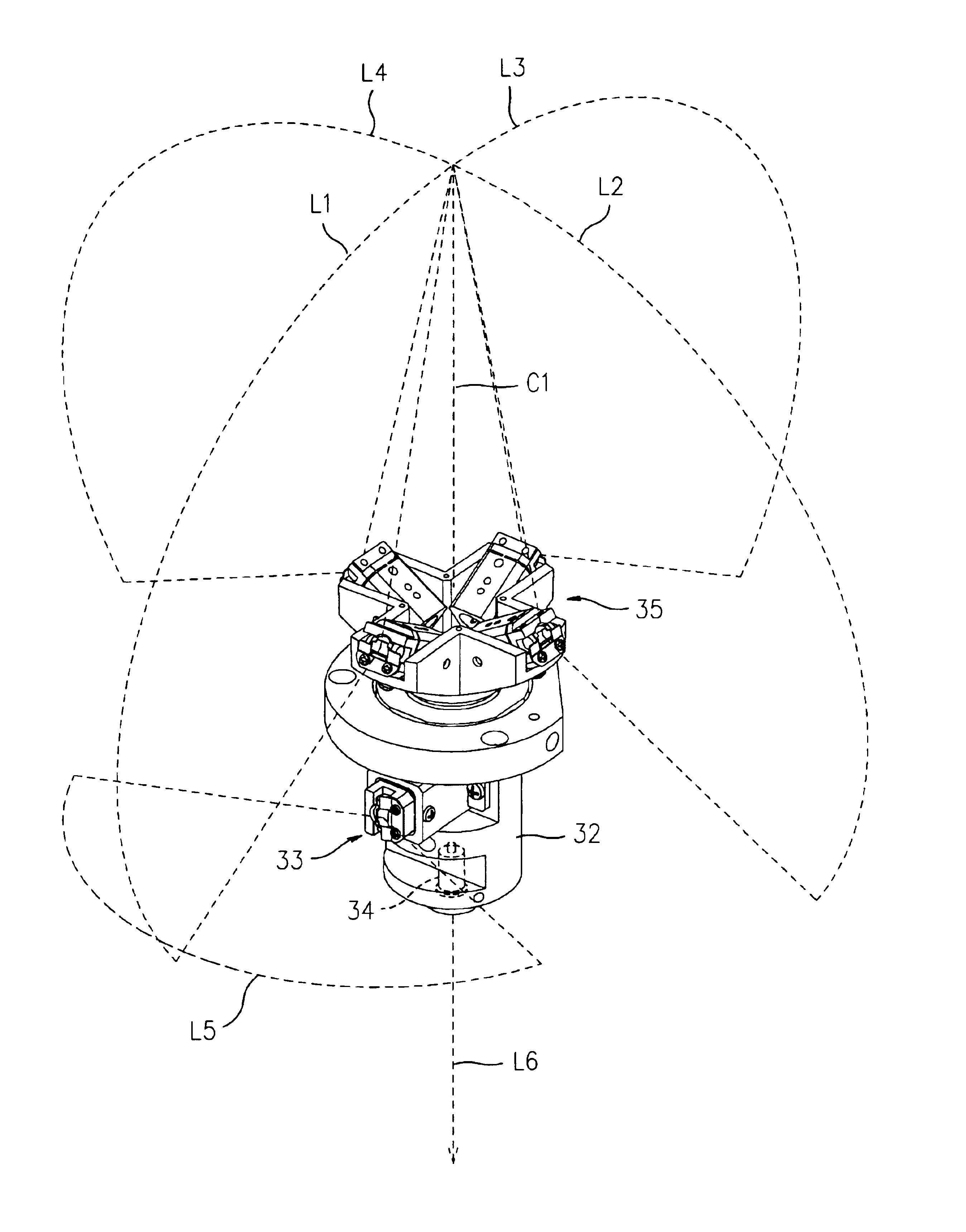
[0027]FIG. 3 illustrates a weight mechanism 30 according to the present invention. The weight mechanism 30 includes a bracket 31, which includes an upper bracket 311, a lower bracket 312, and a plurality of supporting struts 313 between the upper bracket 311 and the lower bracket 312. A weight 32 is installed inside the bracket 31, with the weight 32 being suspended naturally by gravity (i.e., like a pendulum) so as to maintain a constant normal between the axial line C1 of the weight 32 and the measuring plane. A stop ring 321 is provided at the bottom of the weight 32, with a conductive ring 322 fitted at the exterior of the weight 32 adjacent t...


PUM


Abstract

A laser indicator includes a weight mechanism having a bracket with a weight secured to the bracket in a manner where the weight is suspended by gravity. A plurality of laser generators are arranged about the weight, including a horizontal beam generator, a center laser generator arranged at the axial center of the bottom of the weight for emitting a laser point coaxial to the axial line of the weight, and a plurality of vertical beam generators positioned in spaced-apart manner around the axial center of the weight at the top of the weight. The laser indicator can include a stand that includes a seat having a plurality of legs, and a rotary table having a plurality of legs, with the weight mechanism coupled to the rotary table, and the rotary table removably coupled to the seat so that altitude of the weight mechanism can be adjusted. In addition, the laser indicator can include a securing mechanism for coupling the weight to the upper bracket of the bracket.

Description

BACKGROUND OF THE INVENTION[0001]1. Field of the Invention[0002]The present invention relates to a multidirectional laser indicator, and in particular, to a multidirectional laser indicator having a simplified adjustment method for adjusting a laser module.[0003]2. Description of the Prior Art[0004]There are many kinds of multidirectional laser indicators available in the current market. One example is illustrated in Republic of China (Taiwan) Patent No. 329,303, entitled “Laser Leveler of Automatic Horizontal Calibration Capability and Convenient Displacement Adjustment”, which has laser units arranged at the front and the four sides (upper, lower, left, and right side) of the projecting platform of the laser leveler for forming a crossing projection using a horizontal and a vertical projecting line, a left and a right vertical projecting line, and upper and lower projecting points.[0005]Another example is illustrated in Republic of China (Taiwan) Patent No. 391,913, entitled “Ink ...

Claims


Application Information

Patent Timeline
IPC IPC(8): G01C15/00
CPCG01C15/004Y10S33/21
Inventor CHANG, SHIH-CHANGWU, SHENG-CHING
Owner QUARTON
Learn More