Portable brake pad measuring tool

a brake pad and measuring tool technology, applied in the direction of mechanical measuring arrangements, instruments, using mechanical means, etc., can solve the problems of inability unwillingness to make a proper evaluation, and the brake pads in vehicles are prone to frictional wear, etc., to facilitate a quick visual indicator of the wear condition of the brake pad, and facilitate the effect of quick visual indication of the wear condition of the brak

Inactive Publication Date: 2005-08-23
IKERD JR TERRY L +1
View PDF24 Cites 26 Cited by
  • Summary
  • Abstract
  • Description
  • Claims
  • Application Information

AI Technical Summary

Benefits of technology

[0024]Each of the rigid bars are further provided with a color-coded bar segment which extends downward a linear length from the bound end thereof. The rigid bars define descending incremental widths which correspond to a specific color cast by each color-coded bar segment so as to provide a quick visual indicator for pad wear condition.
[0025]A flattened heel portion of each right-angled foot segment is placed in flush engagement against an outer periphery of a selected brake pad. Each right-angled foot segment is powder-coated with a light colored boot in order to provide a sharp contrast in color with respect to the boot and brake pad, thereby facilitating a quick visual indication of pad wear condition. The design and configuration of the brake pad measuring tool 10 allows for a brake pad's condition to be determined while vehicle wheel is still attached to hub. Brake pad condition is determined through random selection of the rigid bars utilizing a trial-and-error approach in order to establish which particular rigid bar provides for an accurate visual indication of brake pad condition.
[0026]The use of the present invention allows for vehicle brake pad life to be measured without requiring vehicle wheel removal in a manner which is quick, easy, and efficient.

Problems solved by technology

Brake pads in vehicles are prone to frictional wear.
The pads wear rather quickly through vehicle usage and require periodic replacement.
However, most individuals are either disinclined or unable to perform such inspection, and still others who are willing lack proficiency to make a proper evaluation.
Neglecting pad wear could result not only in inconvenience and extreme expense, but could result in ultimate brake failure, thus leading to an accident.

Method used


Image

  • Portable brake pad measuring tool
  • Portable brake pad measuring tool
  • Portable brake pad measuring tool

Examples


Embodiment Construction

1. Detailed Description of the Figures

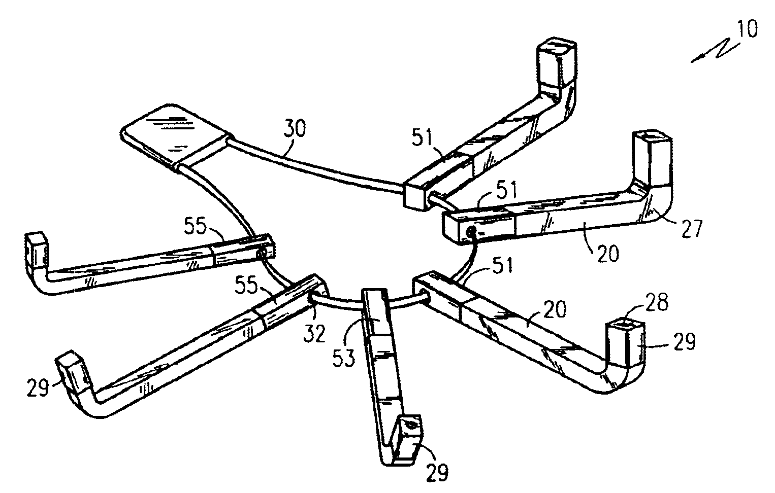
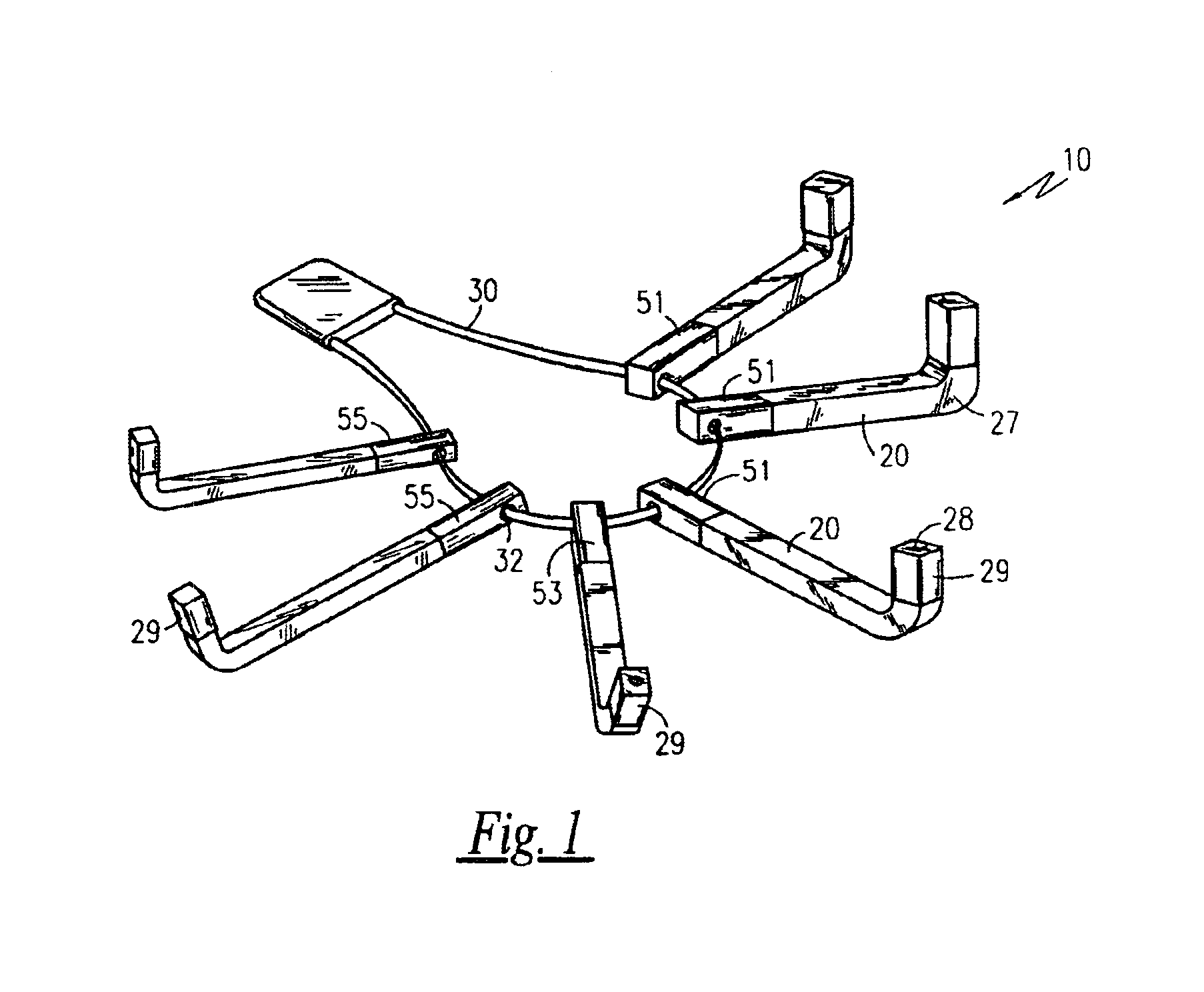
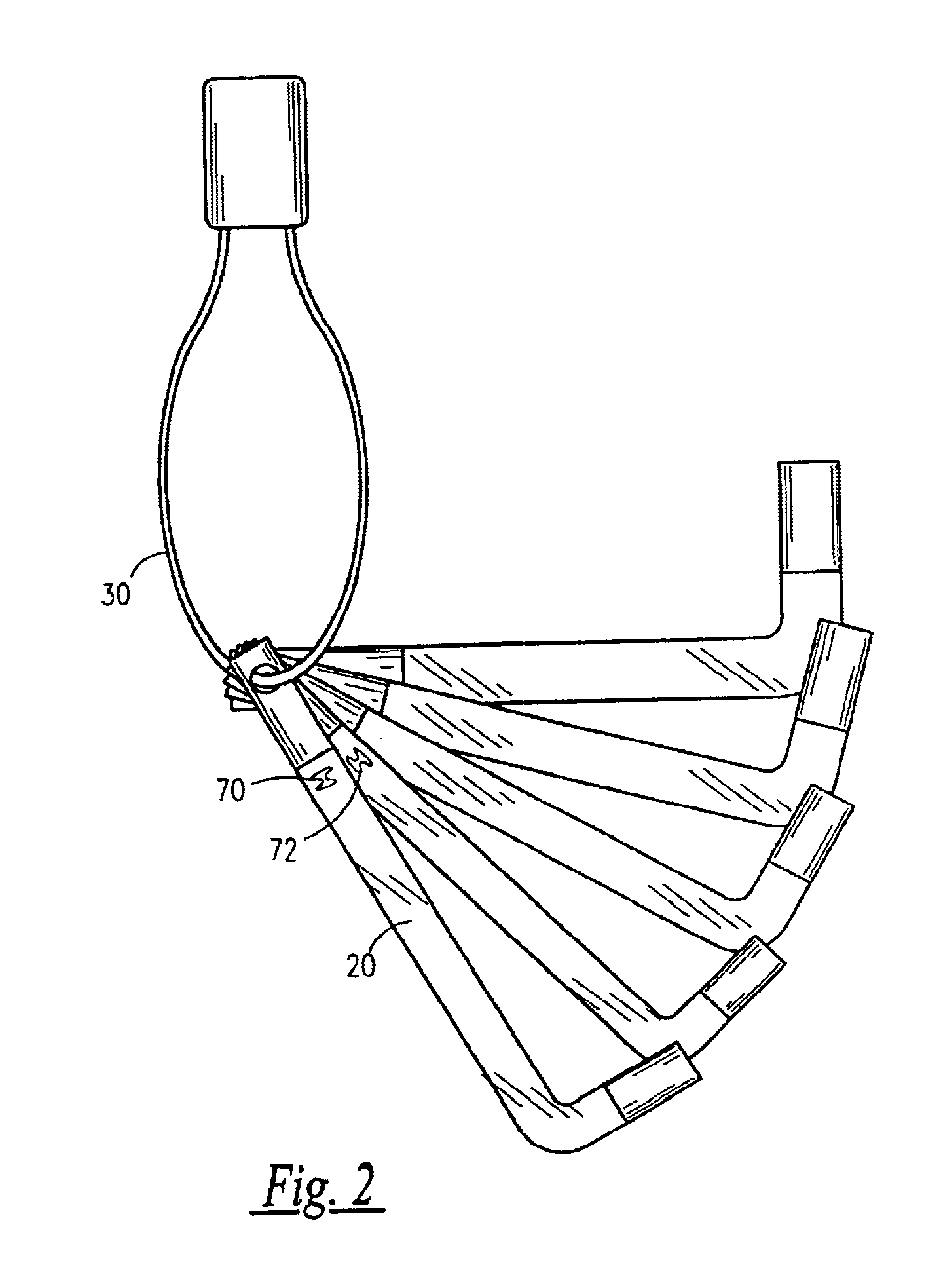
[0033]Referring now to FIGS. 1-5, a brake pad measuring tool 10 is shown, according to the present invention, comprised of a plurality of rigid bars 20, each defining an elongated, rectangular configuration, and being attached in a reciprocal and rotatable manner via a coupling ring 30. For purposes of this disclosure, six rigid bars 20 are described and illustrated, however, the number of rigid bars 20 is envisioned as being variable, and thus the number shown herein is not intended to be a limiting factor.

[0034]Each of the rigid bars 20 are further defined as generally straight and having a free end 22 opposing a bound end 26. A ring-receiving hole 32 extends horizontally through each of the rigid bars 20 along the bound end 26 thereof, through which the coupling ring 30 is threaded, thereby holding the rigid bars 20 in an efficient and organized manner.

[0035]The free end 22 of the rigid bars 20 has a right-angled foot segment 27 which include...


PUM


Abstract

A brake pad measuring tool is disclosed and functions to provide a quick visual indicator for determining brake pad wear condition in motor vehicles. The brake pad measuring tool includes a plurality of rigid bars which are attached in a reciprocal and rotatable manner via a coupling ring. Each of the rigid bars has a free end provided with a color-coded bar segment. The rigid bars also have descending incremental widths which correspond to a specific color cast by each color-coded bar segment, thus serving as a quick visual indicator for pad wear condition. The brake pad measuring tool allows for a brake pad's condition to be determined while the vehicle wheel is still attached to the hub.

Description

RELATED APPLICATIONS[0001]The present invention was first described in Disclosure Document Deposit Request mailed on Jul. 24, 2003 for registration under 35 U.S.C. §122, 37 C.F.R. §1.14, and MPEP §1706. There are no previously filed, nor currently any co-pending applications, anywhere in the world.BACKGROUND OF THE INVENTION[0002]1. Field of the Invention[0003]The present invention relates generally to devices for measuring brake pad wear and, more particularly, to a portable brake pad measuring tool.[0004]2. Description of the Related Art[0005]Brake pads in vehicles are prone to frictional wear. The pads wear rather quickly through vehicle usage and require periodic replacement. Drivers typically rely upon dashboard warning lights or the squeal emanating from the brakes to alert them of excessive brake pad wear. An inspection of the brake pads requires the tedious removal of the wheel from the vehicle hub in order to perform a visual test to; determine pad wear condition. However, ...

Claims


Application Information

Patent Timeline
Patent Type & Authority Patents(United States)
IPC IPC(8): G01B3/30G01B5/00
CPCF16D65/0043G01B3/30G01B5/0028
Inventor IKERD, JR., TERRY L.JOHNSON, NELS
Owner IKERD JR TERRY L
Why Eureka
Try Eureka