Dehumidifier as effected by moisture exchange

Inactive Publication Date: 2005-08-23
HSU TSANG HUNG
View PDF8 Cites 19 Cited by
  • Summary
  • Abstract
  • Description
  • Claims
  • Application Information

AI Technical Summary

Benefits of technology

[0003]The object of the present invention is to provide a dehumidifier including: a housing, a fan axially mounted in the housing along a longitudinal axis of the housing, and a moisture-exchange device having a plurality of thin flat air-penetrable ducts radially disposed in the housing and having a dehydrating chamber filled with des

Problems solved by technology

However, such a dehumidifier can only absorb water vapor from ambient air very near the dehumidifier.
Except that a forced-draft air circulation system or mechanism is provided to increa

Method used


Image

  • Dehumidifier as effected by moisture exchange
  • Dehumidifier as effected by moisture exchange
  • Dehumidifier as effected by moisture exchange

Examples


Embodiment Construction

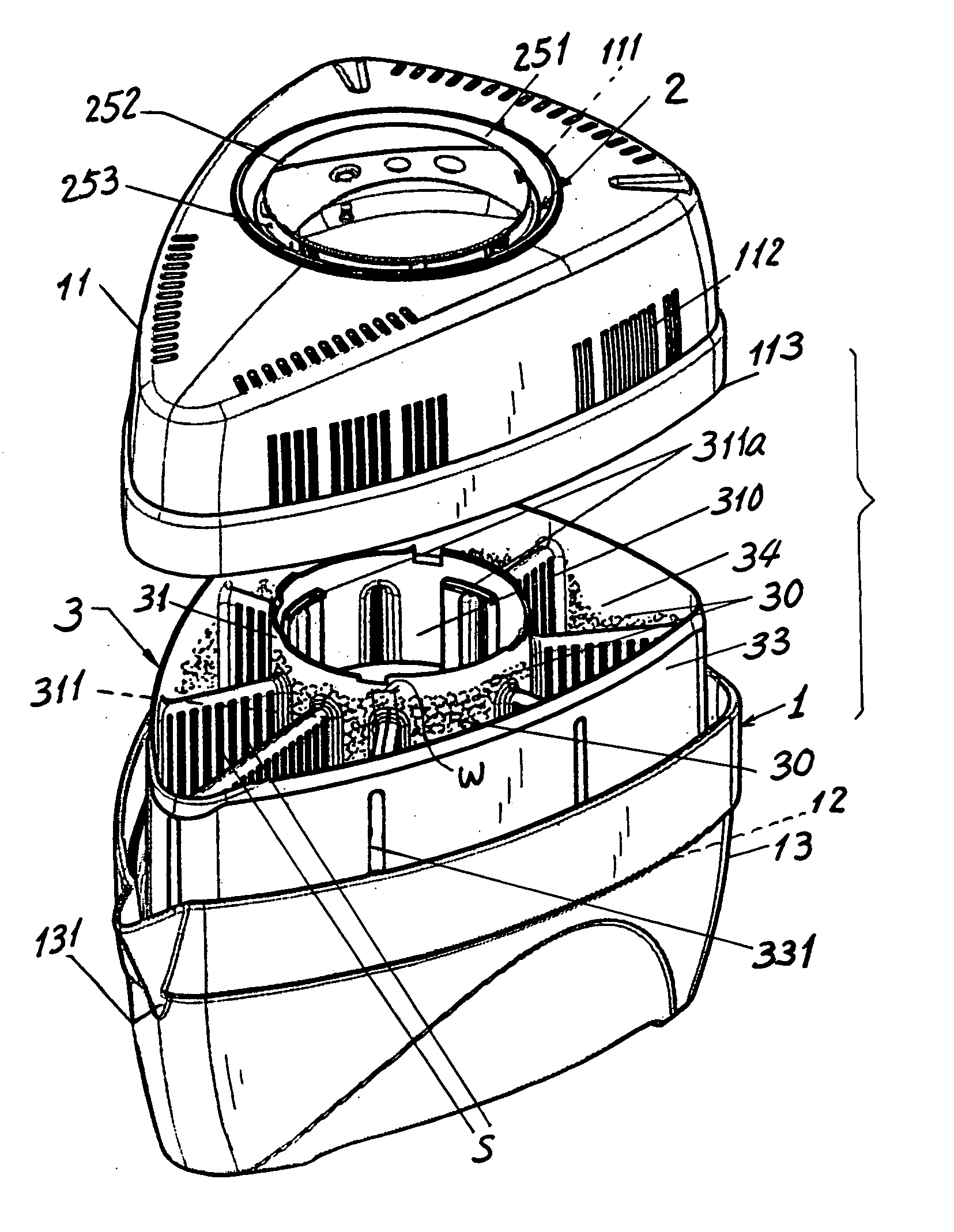
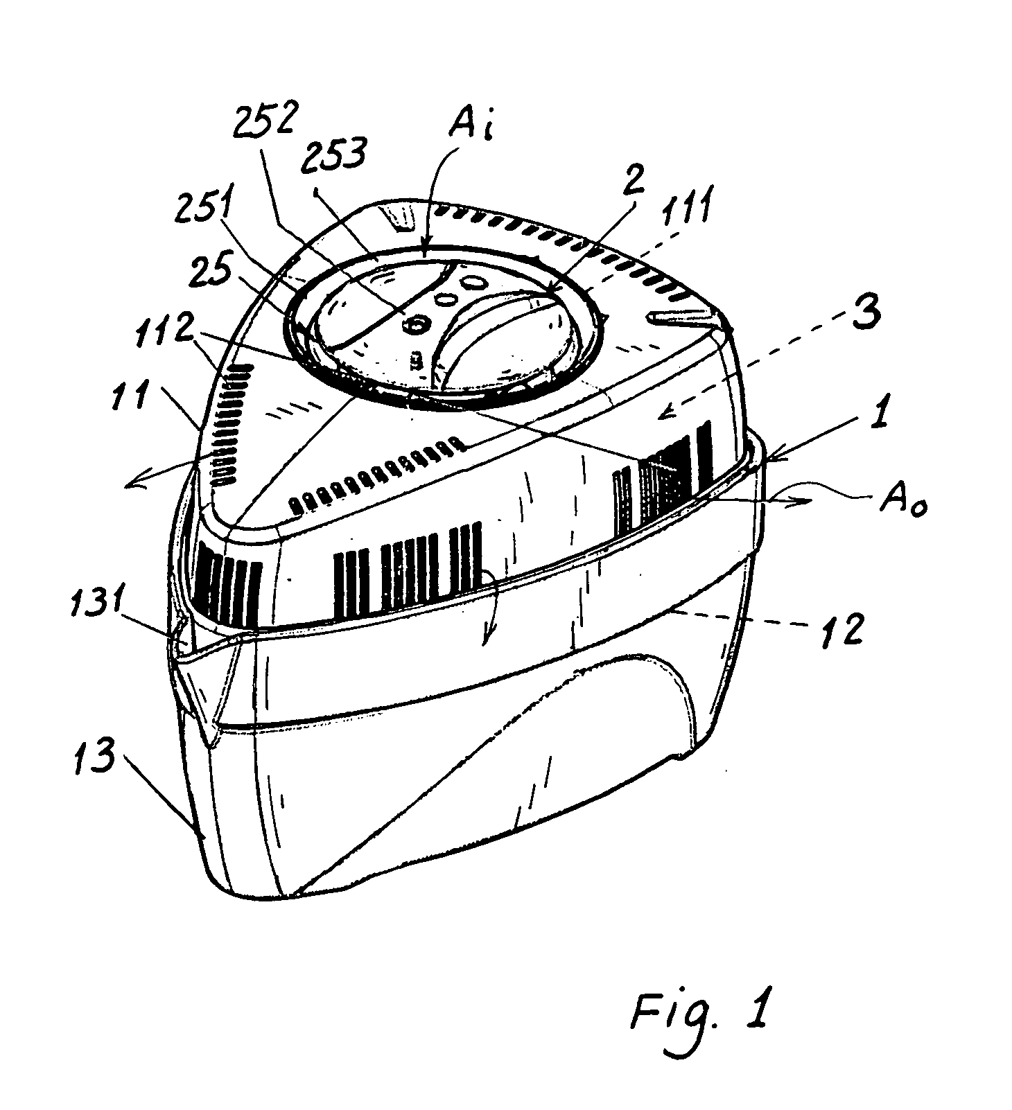
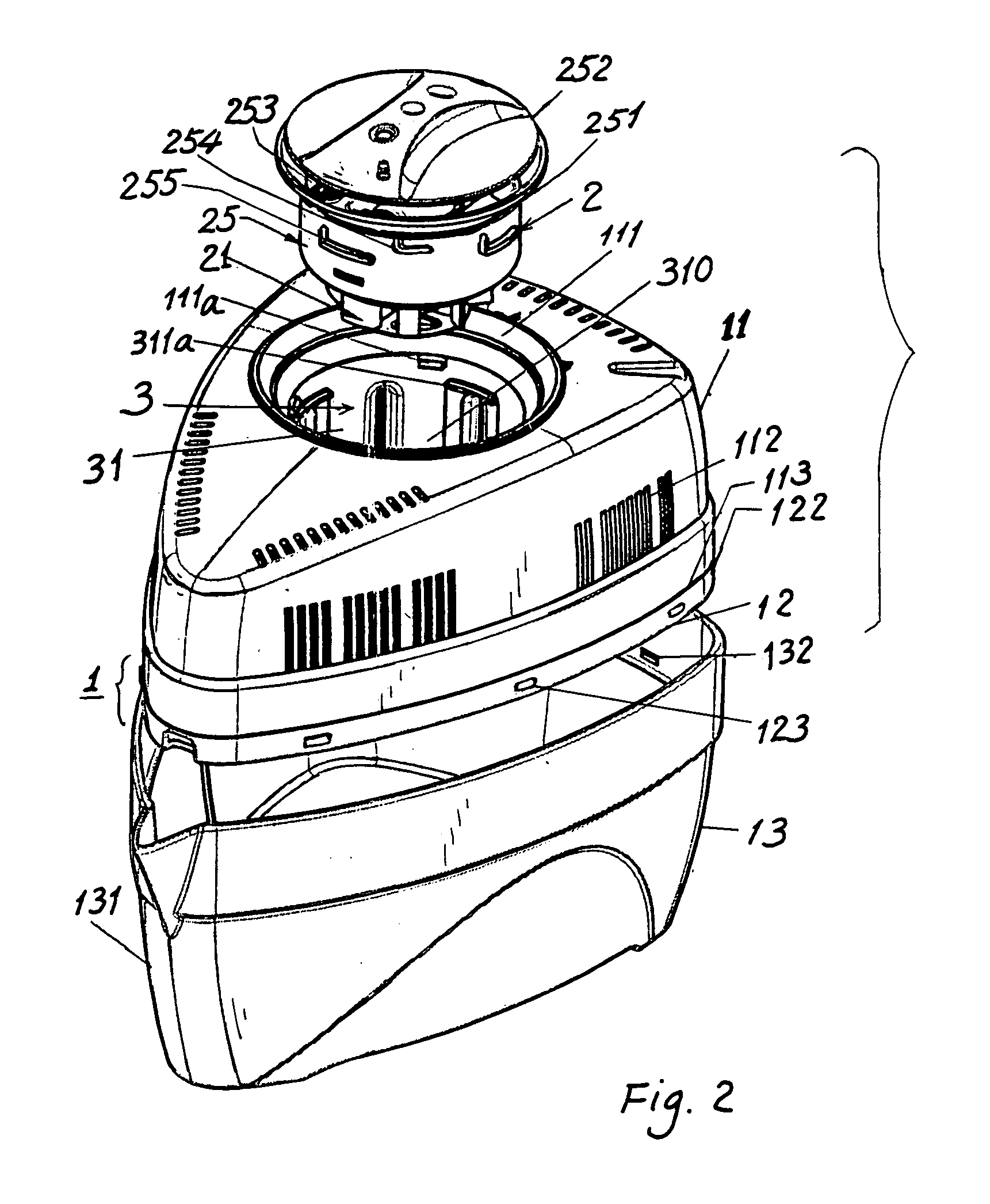
[0010]As shown in the drawing figures, the dehumidifier of the present invention comprises: a housing 1, a fan device 2 axially and detachably mounted in the housing 1 along a longitudinal axis X defined at a longitudinal center of the housing 1, and a moisture-exchange device 3 formed in between the fan device 2 and the housing 1. Even a triangular-like shape of the outer appearance of the present invention is shown in the drawings, the shapes of the present invention are however not limited. The present invention is preferably made as a portable dehumidifier for its convenient uses in a room, a cabinet, a closed container, and so on.

[0011]The housing 1 includes: an outer shell 11, a sieve plate 12 engaged with a lower edge portion of the outer shell 11, and a basin 13 detachably secured to a bottom rim of the sieve plate 12.

[0012]The outer shell 11 includes an upper conical portion 111 formed in an upper central portion of the shell 11 for receiving an upper hopper portion 251 of ...


PUM


Abstract

A dehumidifier includes: a housing, a fan axially mounted in the housing along a longitudinal axis of the housing, and a moisture-exchange device having a plurality of thin flat air-penetrable ducts radially disposed in the housing and having a dehydrating chamber filled with desiccant material in the chamber between the fan and an outer shell of the housing; whereby the ambient air will be drafted by the fan and blown radially outwardly by the fan through the air-penetrable ducts to allow the desiccant material to absorb the moisture as laden in the air through the ducts for efficiently dehumidifying the air.

Description

BACKGROUND OF THE INVENTION[0001]U.S. Pat. No. 4,756,726 to Terry Peace disclosed a dehumidifier device comprising a container comprised of several elongated compartments in parallel juxtaposition and desiccant granules confined within the container for absorbing moisture for dehumidification purpose. However, such a dehumidifier can only absorb water vapor from ambient air very near the dehumidifier. Except that a forced-draft air circulation system or mechanism is provided to increase the contacting opportunity of the ambient air with such a dehumidifier, the water absorption rate by the dehumidifier is quite low, thereby affecting its dehumidification efficiency.[0002]The present inventor has found the drawbacks of the prior art and invented the present dehumidifier having increased dehumidification efficiency.SUMMARY OF THE INVENTION[0003]The object of the present invention is to provide a dehumidifier including: a housing, a fan axially mounted in the housing along a longitudin...

Claims


Application Information

Patent Timeline
IPC IPC(8): F26B21/06B01D53/26F24F3/14
CPCB01D53/261F24F3/1411F24F2203/028
Inventor HSU, TSANG-HUNG
Owner HSU TSANG HUNG
Why Eureka
Try Eureka