
Valve apparatus for hermetic compressor

a valve apparatus and compressor technology, applied in the direction of machines/engines, liquid fuel engines, positive displacement liquid engines, etc., can solve the problems of large noise generation and opening delay phenomena, and achieve the effect of improving compressor efficiency and minimizing noise generated during compressor operation

Inactive Publication Date: 2005-08-23
LG ELECTRONICS INC
View PDF9 Cites 3 Cited by
  • Summary
  • Abstract
  • Description
  • Claims
  • Application Information

AI Technical Summary

Benefits of technology

[0009]The present invention is contemplated to solve the aforementioned problems in the prior art. An object of the present invention is to minimize noise generated from a valve apparatus of the present invention during the operation of a compressor.
[0010]Another object of the present invention is to maximize efficiency of a compressor.
[0024]According to the valve apparatus of the hermetic compressor of the present invention constructed as such, there are advantages in that the noise generated during the operation of the compressor can be minimized and the compressor efficiency can be improved.

Problems solved by technology

As described above, however, since the tip portions of the valves repeatedly strike the valve seat during the operation of the compressor so that the flow passage can be opened and closed, a large amount of noise is generated.
Further, inappropriate shapes of the valve seat and the flow passage formed in the valve plate can cause the opening delay phenomena to occur.

Method used


Image

  • Valve apparatus for hermetic compressor
  • Valve apparatus for hermetic compressor
  • Valve apparatus for hermetic compressor

Examples


Embodiment Construction

[0035]Hereinafter, preferred embodiments of the present invention will be described in detail with reference to the accompanying drawings.

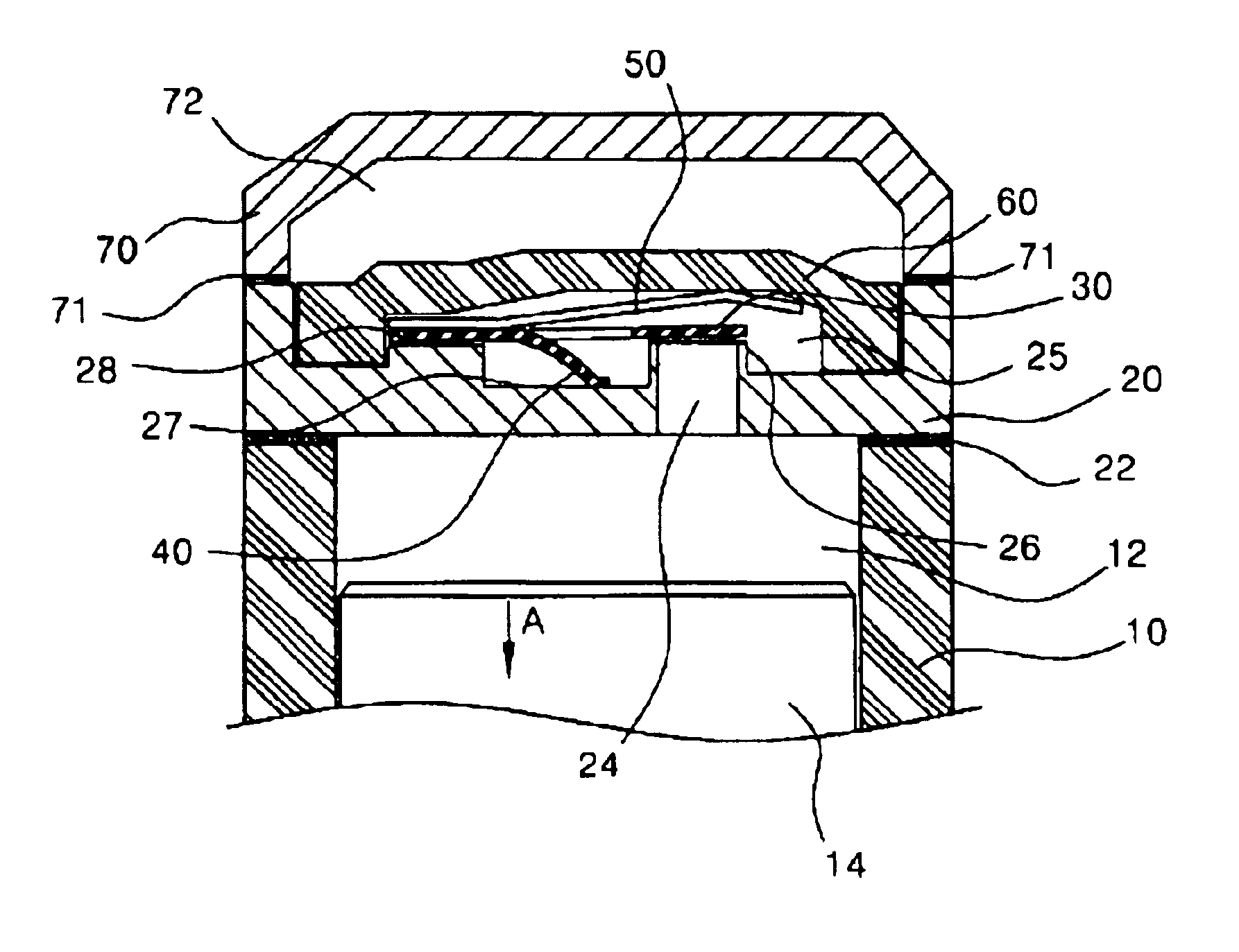
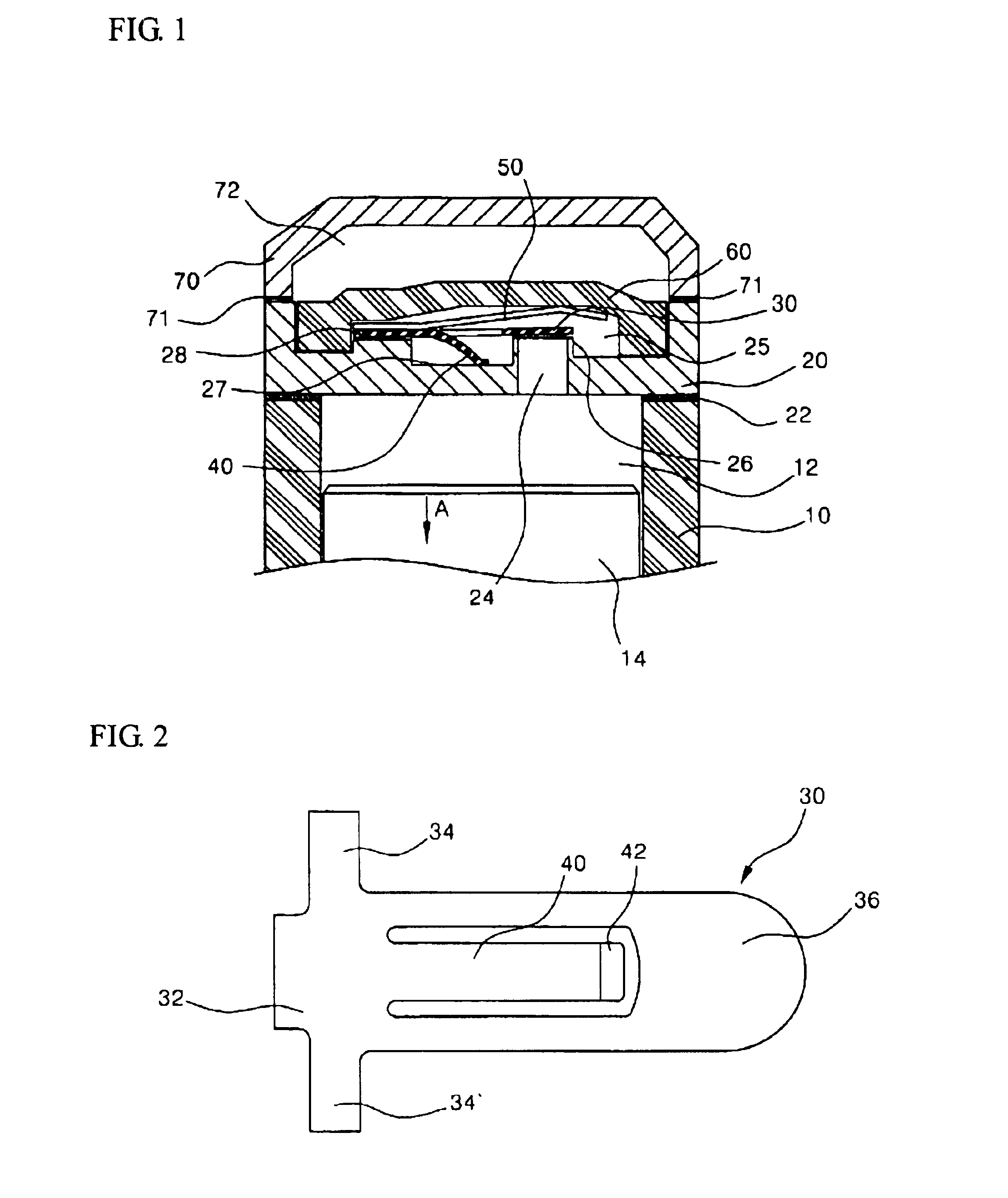
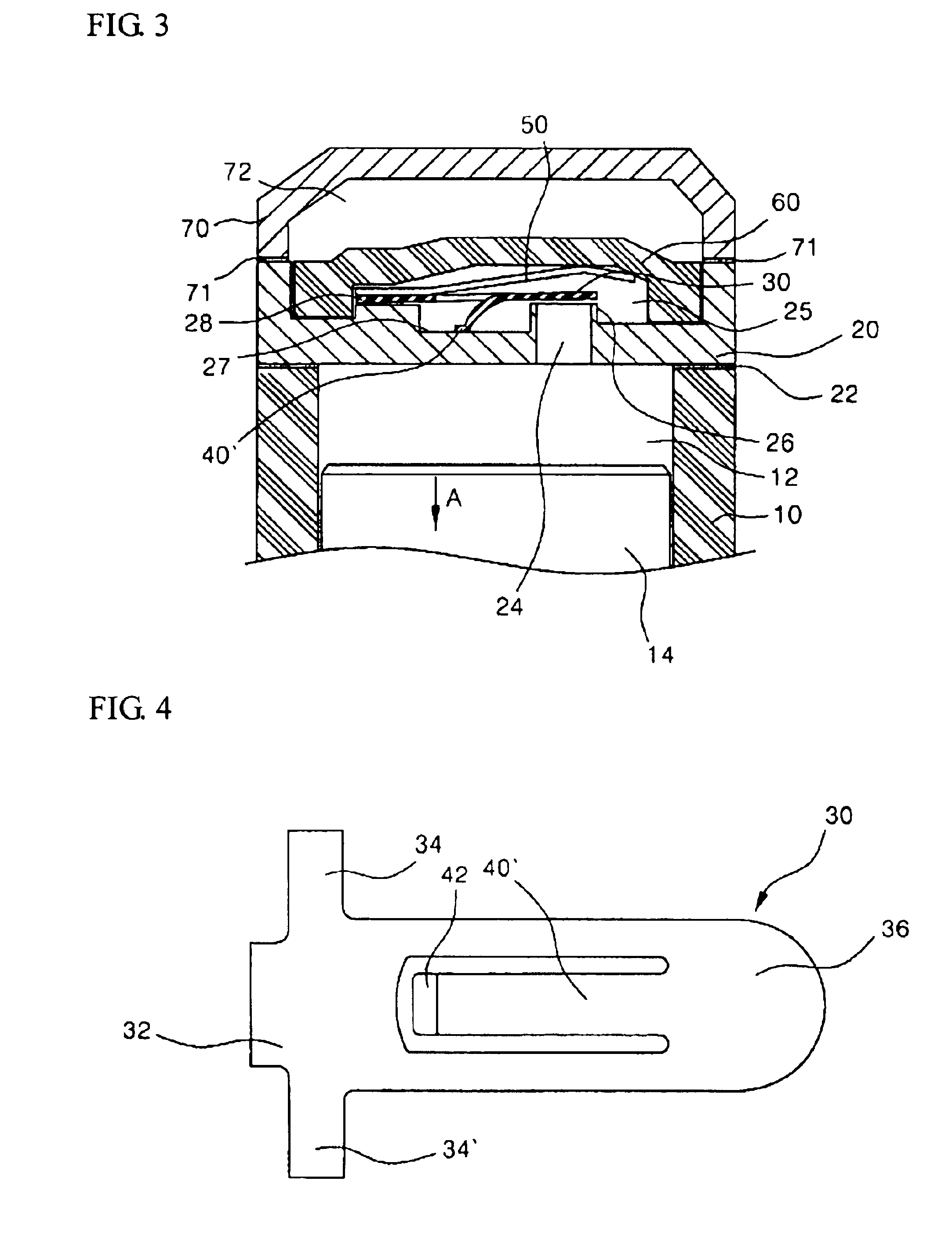
[0036]Referring to FIG. 1, a compression chamber 12 in which compression of working fluid is performed is formed within a cylinder block 10. A reciprocating piston 14 is installed within the compression chamber 12. The piston 14 reciprocates linearly within the compression chamber 12 by means of driving force generated from a motor unit that is a component of the hermetic compressor.

[0037]A valve plate 20 is installed onto a leading end of the cylinder block 10. The valve plate 20 is mounted to the cylinder block 10 with a gasket interposed between the valve plate and a front face of the cylinder block 10. A flow passage 24, which is formed through the valve plate 20, has a function of communicating the compression chamber 12 with a discharge chamber 72 to be described later. The flow passage 24 perforates into a valve chamber 25 formed onto a sid...


PUM


Abstract

The present invention relates to a valve apparatus for a hermetic compressor. In the present invention, an elastic lead (40) is integrally formed with a discharge valve (30) in order to reduce striking force generated when the discharge valve (30) strikes a valve seat (26) and to facilitate opening of the discharge valve (30). The elastic lead (40) is formed by cutting out an intermediate portion of the discharge valve (30), and a free end of the elastic lead is bent to directed to a free end (36) or a clasped portion (32) of the discharge valve (30). The free end (36) of the elastic lead (40) is supported on a bottom surface of a recess (27) in a valve plate (20), and thus, the elastic lead (40) exerts elastic force on the discharge valve (30) in a direction that the discharge valve (30) is opened. According to the present invention constructed as such, noise generated when the discharge valve (30) operates can be minimized, and opening / closing operation of the discharge valve (30) can be smoothly performed.

Description

TECHNICAL FIELD[0001]The present invention relates to a hermetic compressor, and more particularly, to a valve apparatus for controlling suction and discharge of working fluid into and out of a cylinder of the compressor.BACKGROUND ART[0002]In a conventional hermetic compressor, a piston linearly reciprocates in a cylinder formed within a cylinder block to compress working fluid. The working fluid can be sucked into and discharged from the cylinder under the control of the valve apparatus.[0003]In general, the valve apparatus is provided on a valve plate which is mounted onto a leading end of the cylinder block to close an interior of the cylinder. A flow passage is formed in the valve plate for communicating the cylinder with the outside (i.e., suction chamber and discharge chamber), and the flow passage is closed or opened by a suction valve or discharge valve. The opening and closing of the suction or discharge valve is performed by means of a difference between the cylinder pres...

Claims


Application Information

Patent Timeline
Patent Type & Authority Patents(United States)
IPC IPC(8): F04B39/10
CPCF04B39/1073Y10T137/7891F16K15/161F16K15/162F16K15/16
Inventor KIM, TAE-MINLEE, HYO-JAE
Owner LG ELECTRONICS INC
Learn More