Thread-supplying device for textile machines

a technology for textile machines and threads, applied in the field of yarn feeders, can solve the problems of relatively simple assembly, and achieve the effect of simple and economical production, reliable operation and simple structur

Inactive Publication Date: 2005-08-23
MEMMINGER IRO GMBH
View PDF13 Cites 11 Cited by
  • Summary
  • Abstract
  • Description
  • Claims
  • Application Information

AI Technical Summary

Benefits of technology

[0007]It is an object of the invention to provide a reliably operable yarn feeder that can be more simply and economically produced.

Problems solved by technology

Assembly is relatively quite uncomplicated.

Method used


Image

  • Thread-supplying device for textile machines
  • Thread-supplying device for textile machines
  • Thread-supplying device for textile machines

Examples


Embodiment Construction

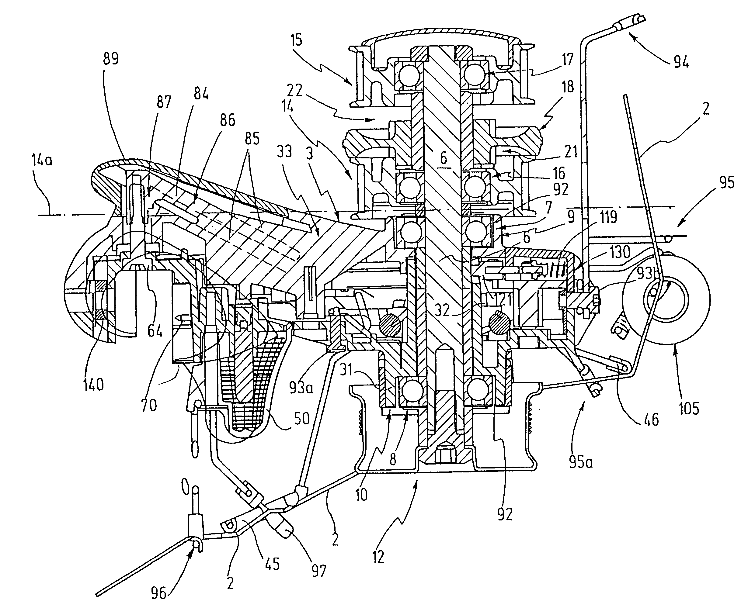
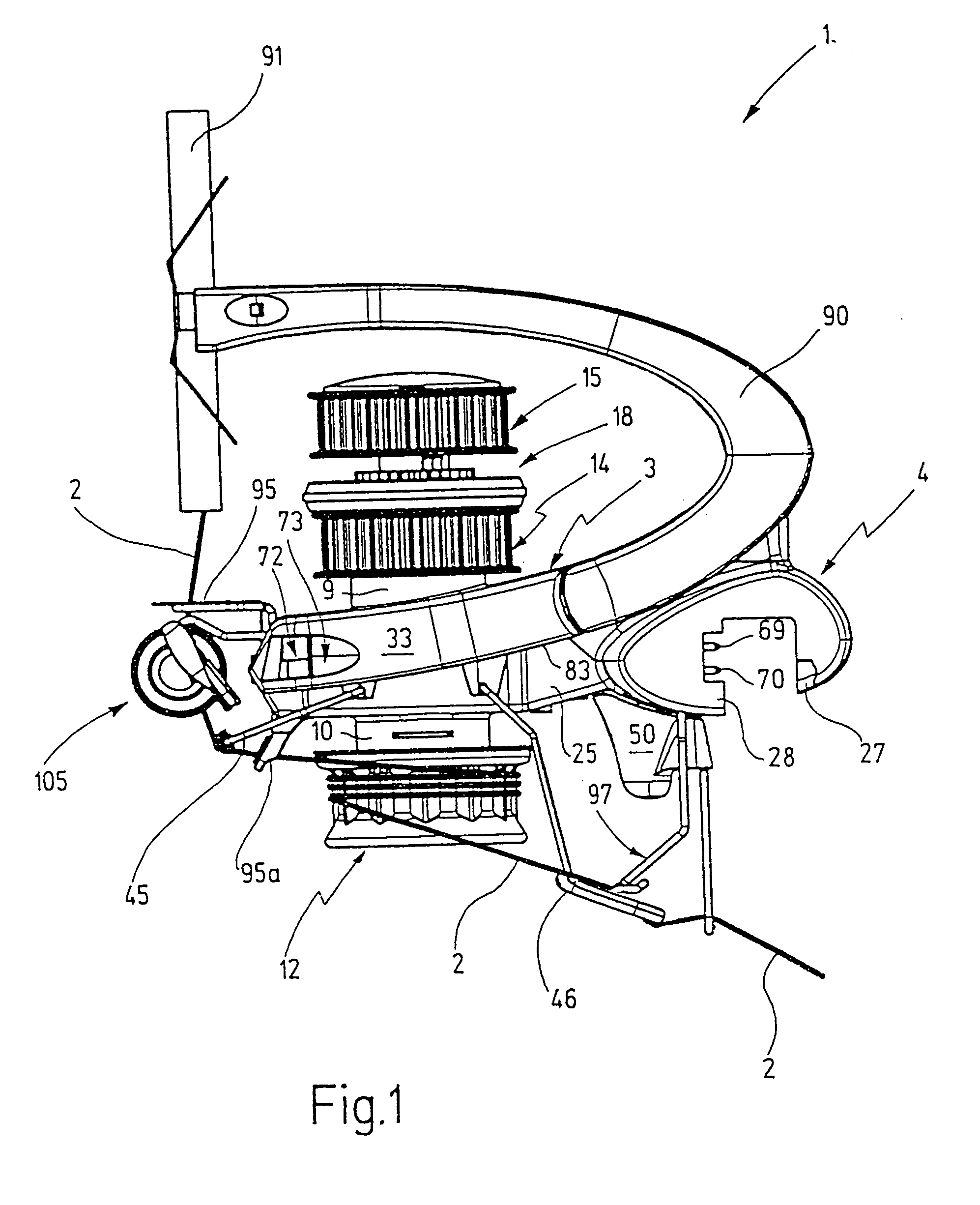
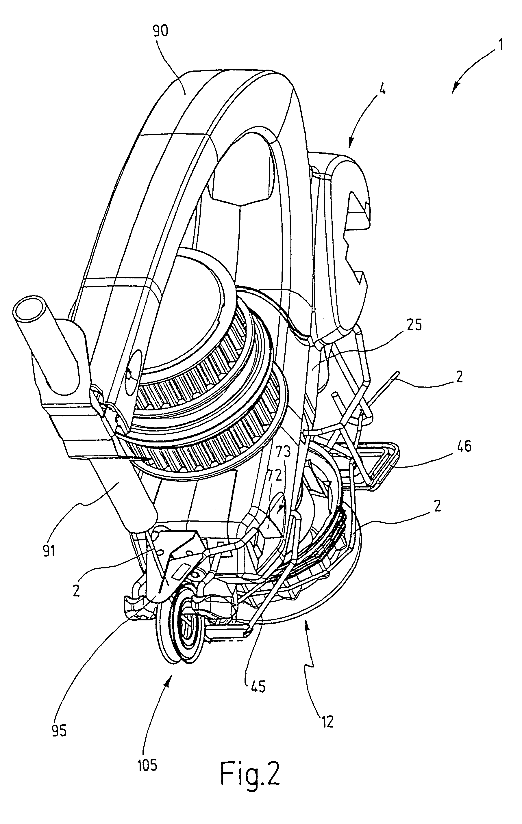
[0034]Referring now more particularly to FIGS. 1 and 2 of the drawings, there is shown an illustrative yarn feeder 1 embodying the present invention adapted for feeding a yarn 2 to a textile-processing machine, such as a knitting machine. The yarn feeder 1 has a housing 3, which serves as a basic carrier for all the elements of the yarn feeder 1. On one end, the housing 3 is provided with a fastening device 4, which is arranged to support and secure the yarn feeder 1 on a suitable retainer 5, such as a rail or a ring of the textile machine. As depicted, the ring may have a rectangular cross section and an electric connection cable laid along its outside. A belt 5a serves to drive all the yarn feeders 1.

[0035]As shown in FIG. 5 (in conjunction with a slightly modified embodiment), a vertically disposed shaft 6 is rotatably supported in the housing 3. For bearing purposes, two ball bearings 7, 8 are used, which are held in respective bearing seats 9, 10 of the housing 3.

[0036]The shaf...


PUM

PropertyMeasurementUnit
electrically groundedaaaaaaaaaa
clamping forcesaaaaaaaaaa
stiffnessaaaaaaaaaa

Abstract

The yarn feeder having a plastic housing, preferably made of two clamshells, with a plastic fastening device for connecting the yarn feeder to a retaining device of a textile machine. The fastening device is made rigid by suitable shaping and without the necessity for metal inlays. The two clamshell halves of the housing each have a bearing for a continuous shaft, which on one end carries a yarn guide drum and on its other end carries pulleys for a drive device. Fasteners serve to hold the two housing parts together in the correct position for enabling easy opening of the housing for maintenance.

Description

FIELD OF THE INVENTION[0001]The invention relates to a yarn feeder [having the characteristics of the preamble to claim 1, 2 or 3].BACKGROUND OF THE INVENTION[0002]Yarn feeders commonly are vendor supplied parts or accessories for textile machines and particularly in loop-forming textile machines are often found in great numbers thereon. The yarn feeders each feed one yarn to a yarn-using station, such as a knitting station. The quality of the knitted goods produced depends decisively on the precision and reliability of the yarn feeders. On the one hand, this demands precision-manufactured yet on the other hand, the yarn feeders should be as simply embodied, economical, and simple to make and maintain as possible. Furthermore, they must perform reliably even if operated for relatively long periods without special maintenance and in particular without cleaning. Deposits of dust or fluff must not impair operation.[0003]The goal also is to design a yarn feeder such that it can be adapt...

Claims


Application Information

Patent Timeline
Patent Type & Authority Patents(United States)
IPC IPC(8): D04B15/38D04B15/48D04B35/14
CPCD04B15/482D04B35/14D04B15/48
Inventor SCHMODDE, HERMANKAUFMANN, RICHARDLEOPOLD, GUNTER
Owner MEMMINGER IRO GMBH
Why Eureka
Try Eureka