Imaging using a coagulable ink on an intermediate member

a technology of intermediate members and inks, applied in the field of digital image recording and printing, can solve the problems of inability to achieve uniform image uniformity, limited image resolution, and relatively high electrical power density for creating electrocoagulated images

Inactive Publication Date: 2005-08-23
EASTMAN KODAK CO
View PDF4 Cites 23 Cited by
  • Summary
  • Abstract
  • Description
  • Claims
  • Application Information

AI Technical Summary

Problems solved by technology

A difficulty inherent in the electrocoagulation technique is that image uniformity requires an extremely accurate distance between each pair of opposing positive and negative electrodes, typically about 50 micrometers.
Moreover, the image resolution is limited by the diameter of individually addressable electrodes and also by the fact that these electrodes must be isolated from one another by a thickness of insulating material between them.
There are other difficulties, e.g. that the electrical power density required for creating an electrocoagulated image is relatively high, that special materials are needed to suppress unwanted gas generation near the electrodes, and that electrodes must be protected against electrolytic erosion.
There are certain limitations, which may be associated with the above-described embodiments.
These limitations include: (1) a difficulty associated with providing a small enough gap, between the operational surface of the intermediate member and the electrocoagulation member, so that every differing amount of electrocoagulable ink in the ink image can be contacted by the electrocoagulation member, i.e., so that electrocoagulation can occur efficiently at every imaging pixel where there is ink; (2) if, in fact, the gap is made thus sufficiently small, there is a difficulty with a possible blurring of the image as a result of a squashing of the large...

Method used


Image

  • Imaging using a coagulable ink on an intermediate member
  • Imaging using a coagulable ink on an intermediate member
  • Imaging using a coagulable ink on an intermediate member

Examples


Embodiment Construction

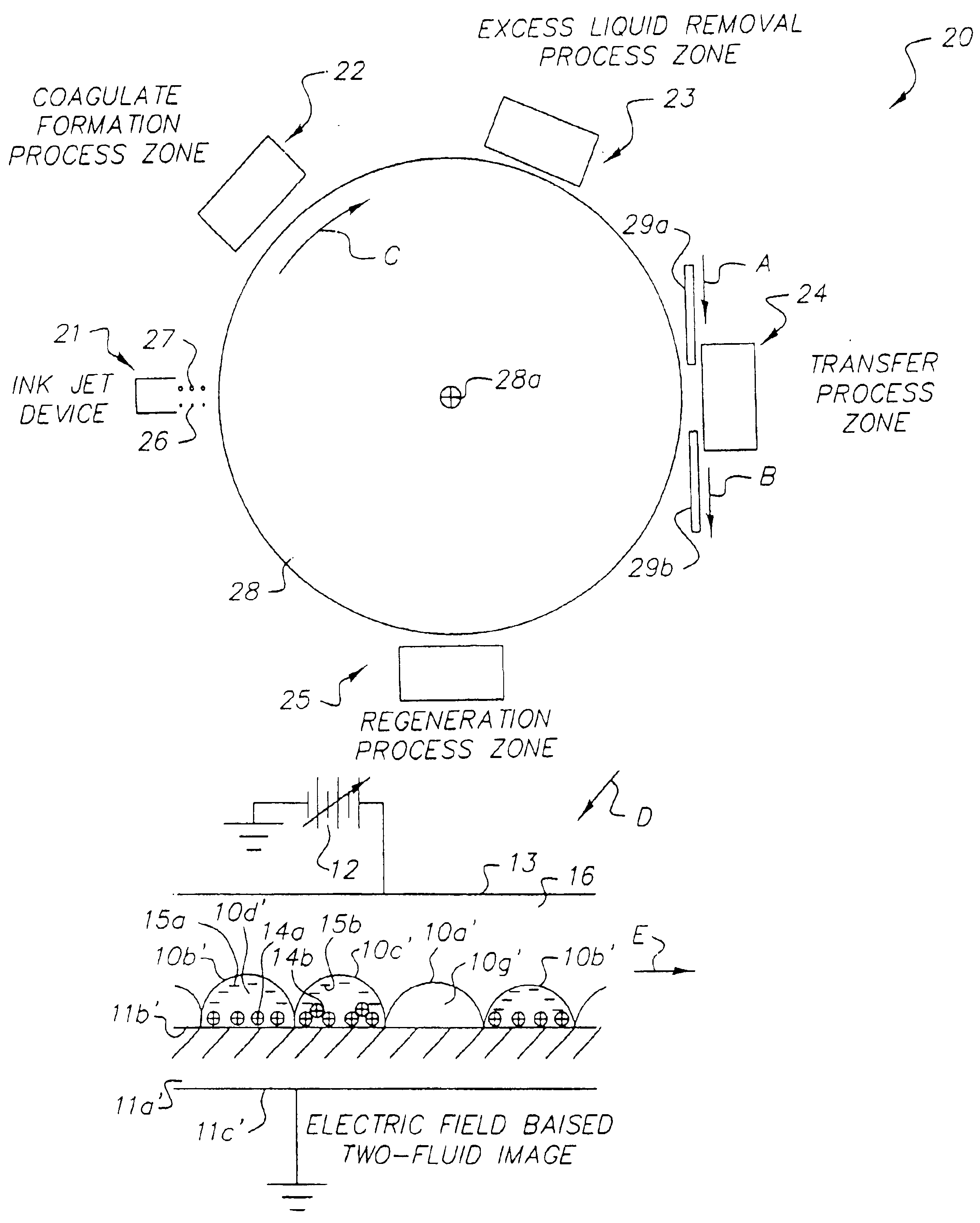
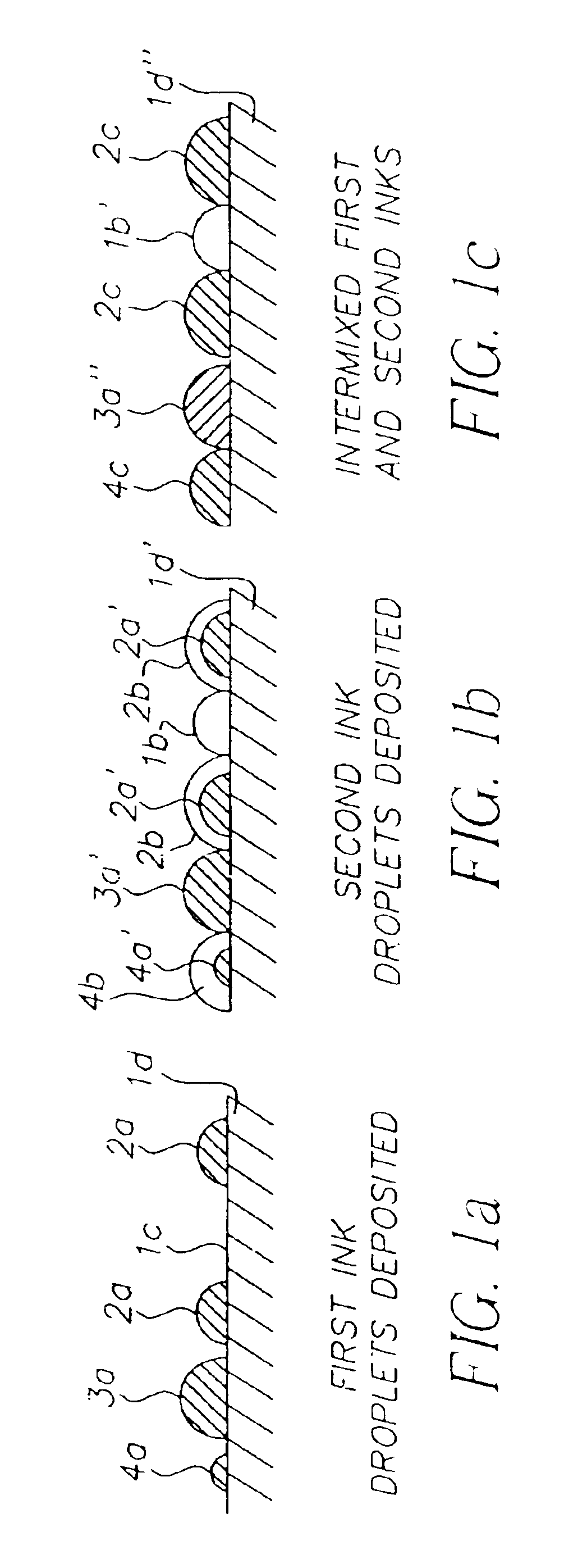
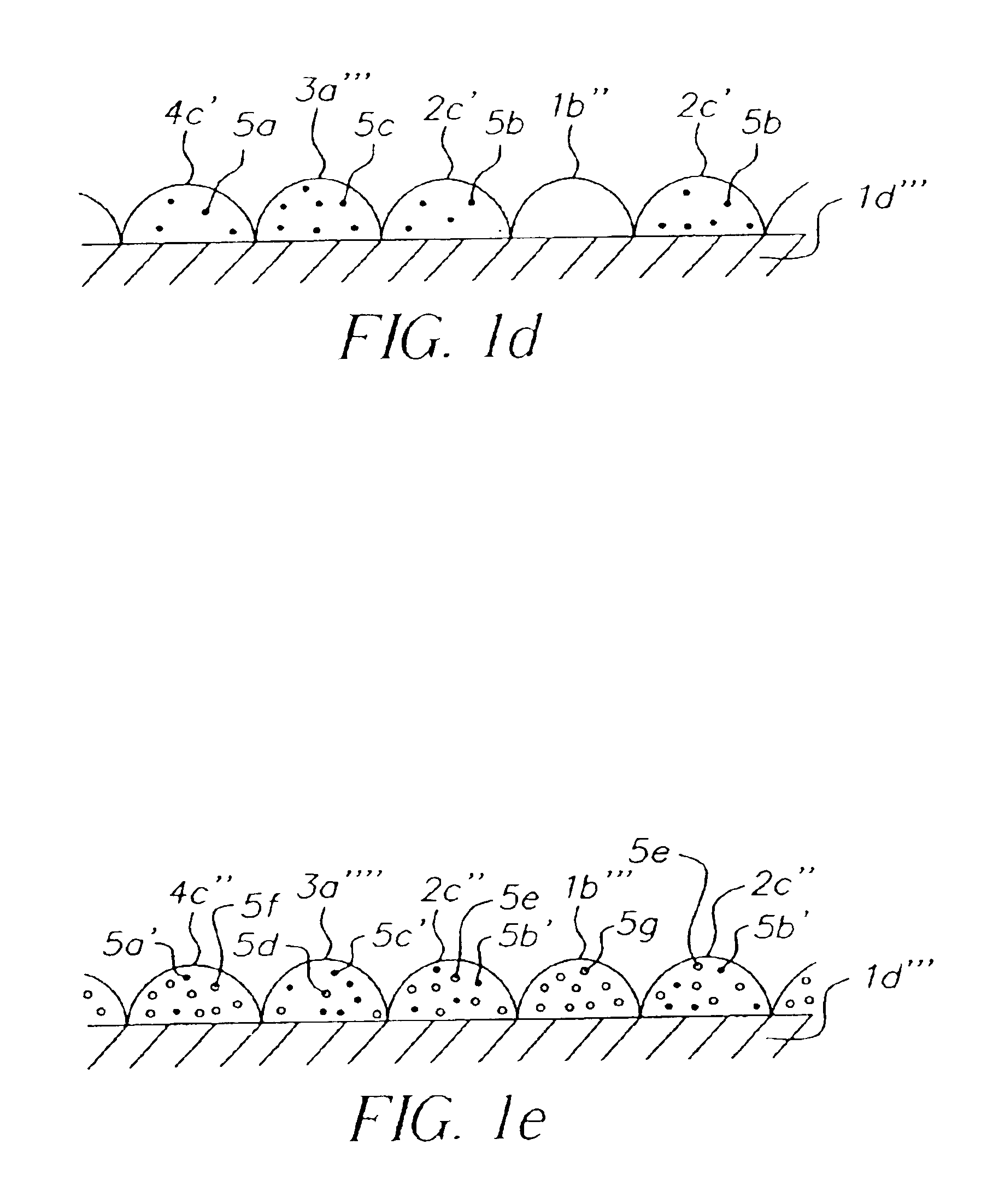
[0023]The invention provides an improved method and apparatus for ink jet imaging, the apparatus employing an ink jet device utilizing a coagulable ink. The ink jet device produces ink droplets according to a known manner for deposition on an intermediate member, which intermediate member has an operational surface upon which a primary ink jet image is formed by the ink jet device. The ink jet device includes a first source of ink for a first ink and a second source of ink for a second ink, of which first and second inks at least one is a marking coagulable ink jet ink. The first ink and the second ink are preferably both nonaqueous, or alternatively are preferably both aqueous-based. The liquid vehicle for an aqueous-based ink is usually water. However, an aqueous-based ink may contain a proportion, typically a minor proportion, of any suitable miscible nonaqueous solvent. In certain embodiments, the marking coagulable ink is a nonaqueous colloidal dispersion of pigmented particles...


PUM

PropertyMeasurementUnit
Flash pointaaaaaaaaaa
Temperatureaaaaaaaaaa
Fractionaaaaaaaaaa

Abstract

Apparatus and method of making an ink-jet-ink-derived material image on a receiver. An ink jet device is used to form a coagulable ink image on a member, the ink image including a coagulable marking ink and a non-marking ink. Each smallest resolved imaging area of the ink image includes a predetermined mixed volume of the coagulable marking ink and the non-marking ink, the predetermined mixed volume being coagulable. Coagulates are formed within the coagulable ink image, and excess liquid is removed from the coagulates to form an ink-jet-ink-derived material image. The ink-jet-ink-derived image is transferred from the operational surface of the intermediate member to another member, which another member may be a receiver member, a drum or a web.

Description

CROSS-REFERENCE TO RELATED APPLICATIONS[0001]Reference is made to the following commonly-assigned copending applications:[0002]U.S. patent application Ser. No. 09 / 973,239, now U.S. Pat. No. 6,719,423 entitled INK JET PROCESS INCLUDING REMOVAL OF EXCESS LIQUID FROM AN INTERMEDIATE MEMBER by Arun Chowdry, et al., and,[0003]U.S. patent application Ser. No. 09 / 973,244, now U.S. Pat. No. 6,682,189 entitled INK JET IMAGING VIA COAGULATION ON AN INTERMEDIATE MEMBER by John W. May, et al., concurrently filed herewith, the disclosures of which are incorporated herein.FIELD OF THE INVENTION[0004]The invention relates in general to digital image recording and printing in an apparatus including an ink jet device for forming an ink image on a member. In particular, a first ink and a second ink are used in the ink jet device wherein at least one of the first and second inks is a coagulable ink, an electric field is applied to the ink image on the intermediate member to form a concentrated image, ...

Claims


Application Information

Patent Timeline
IPC IPC(8): B41J2/01B41M5/00
CPCB41J2/01B41J2002/012
Inventor MAY, JOHN WALTERCHOWDRY, ARUNTOMBS, THOMAS NATHANIEL
Owner EASTMAN KODAK CO
Why Eureka
Try Eureka