Easily installable optical position transducer and keyboard musical instrument having the same

a technology of optical position transducer and keyboard, which is applied in the direction of instruments, electrophonic musical instruments, optical radiation measurement, etc., can solve the problems of time-consuming installation work, complicated installation work, and increase the production cost of composite keyboard musical instruments, and achieve the effect of convenient installation

Inactive Publication Date: 2005-08-23
YAMAHA CORP
View PDF14 Cites 24 Cited by
  • Summary
  • Abstract
  • Description
  • Claims
  • Application Information

AI Technical Summary

Benefits of technology

[0015]It is therefore an important object of the present invention to provid

Problems solved by technology

When the pianist plays a piece of music through the acoustic tones, he or she disables the automatic playing system, and does not give any piece of music data information to the automatic playing system.
A problem is encountered in the prior art optical position transducers in the installation work.
The installation work is complicated.
The work

Method used


Image

  • Easily installable optical position transducer and keyboard musical instrument having the same
  • Easily installable optical position transducer and keyboard musical instrument having the same
  • Easily installable optical position transducer and keyboard musical instrument having the same

Examples


first embodiment

[0034]Composite Musical Instrument

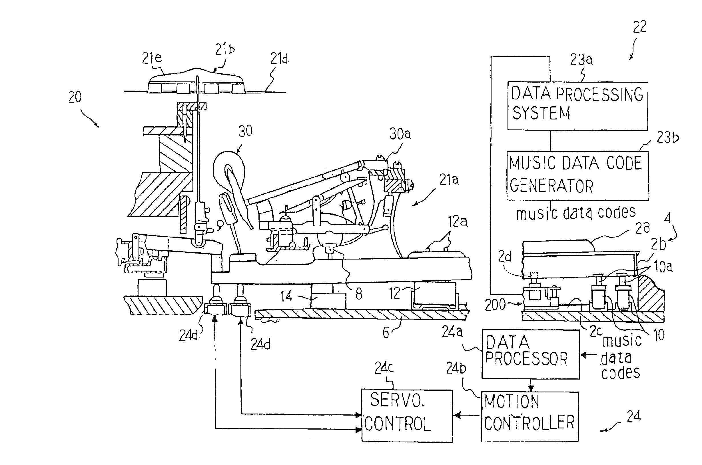
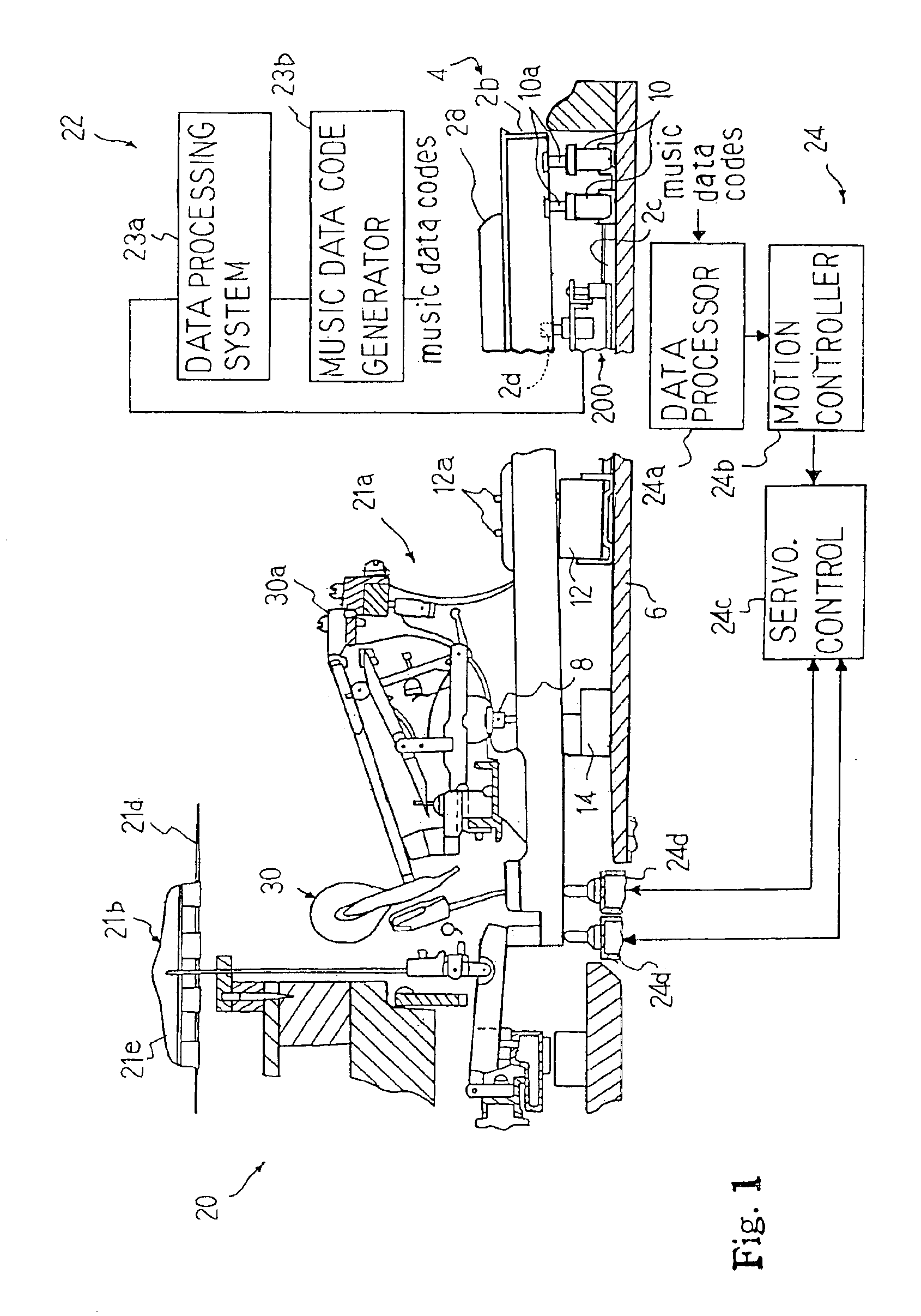
[0035]Optical transducers according to the present invention are available for the composite musical instrument. An automatic player piano is an example of the composite keyboard musical instrument, and is hereinbelow described with reference to FIG. 1. In the following description, word “front” is indicative of a side near to the player of the musical instrument and word “rear” is indicative of a side far from the player of the musical instrument. Word “fore-and-aft direction” is the direction in which black keys and white keys generally extend from the rear side to the front side. Word “lateral” is indicative the direction crossing the line of the general arrangement of black / white keys in the standard acoustic piano. In other words, the lateral direction crosses the fore-and-aft direction at 90 degrees, respectively.

[0036]The automatic player piano embodying the present invention largely comprises an acoustic piano 20, a recording system 22 and a...

second embodiment

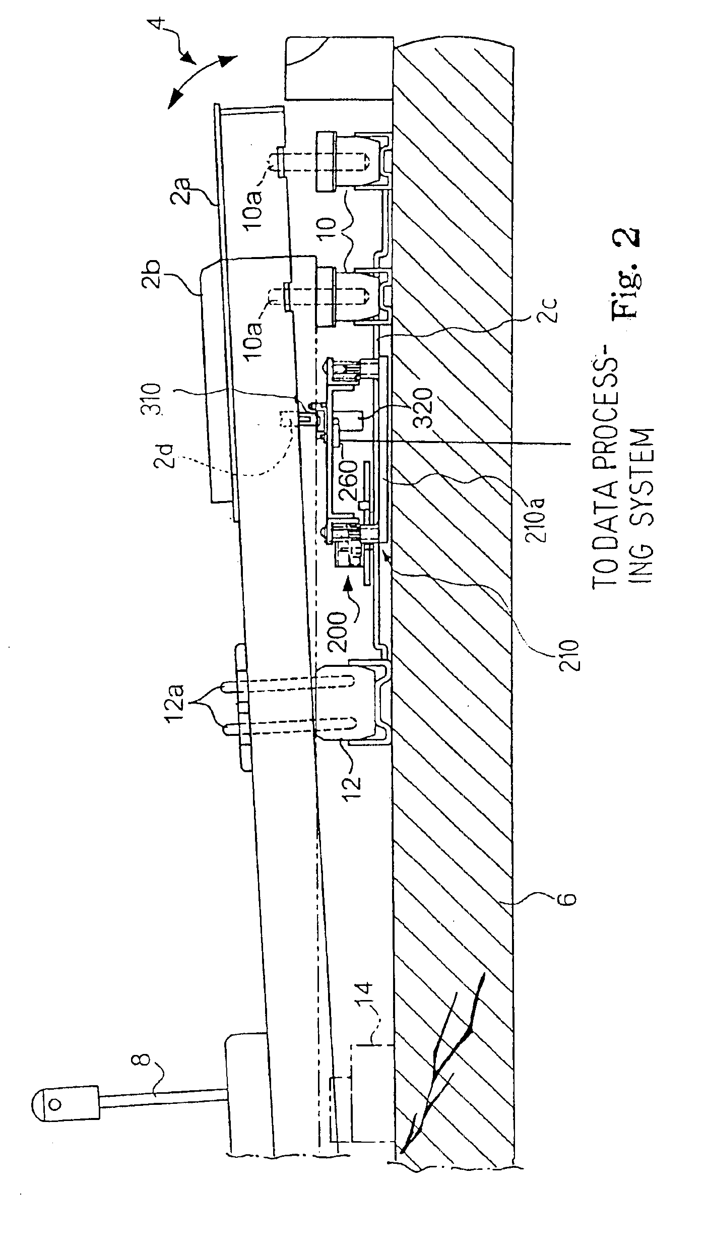
[0078]FIGS. 7 and 8 illustrate an optical filter 320B forming a part of another optical position transducer 200B embodying the present invention. The optical position transducer 200B is available for the composite keyboard musical instrument.

[0079]The optical position transducer implementing the second embodiment includes a photo-coupler 260A, a coupler 310B and the optical filter 320B. The photo-coupler 260 may be same as that in the optical position transducer 200a, i.e., the combination of a pair of optical sensor heads, optical fibers and light emitting / light detecting elements. In case where the optical position transducer 200B is used in an automatic player piano, the optical position transducer 200B serves as a key sensor unit, and the key sensor units may be secured to the reverse surface of the supporting frame 210.

[0080]The coupler 310B and the optical filter 320B are monolithic, and the monolithic body 310B / 320B is formed of transparent substance such as synthetic resin. ...


PUM


Abstract

An optical position transducer is provided for each of the black/white keys incorporated in a composite keyboard musical instrument; the optical position transducer includes a photo-coupler radiating a light beam, an optical filter moved across the light beam, a recess formed in the black/white key at a proper position where the optical filter is aligned with a target trajectory crossing the light beam and an elastic coupler pressed to an inner surface defining the recess and secured to the optical filter so that a worker assembles the optical filter with the key by inserting the elastic coupler into the recess.

Description

CROSS-REFERENCE TO RELATED APPLICATION[0001]This application is a division of application Ser. No. 10 / 199,256 filed on Jul. 18, 2002, which application is specifically incorporated herein, in its entirety, by reference.FIELD OF THE INVENTION[0002]This invention relates to a data acquisition technology preferable for a moving object on a certain trajectory and, more particularly, to an optical position transducer and a keyboard musical instrument with the optical position transducers for obtaining pieces of music data information.DESCRIPTION OF THE RELATED ART[0003]Musical instruments are classified into two major categories. Acoustic musical instruments are categorized in the first group. Players give rise to vibrations in the acoustic musical instruments, and the acoustic sound is generated directly from the vibrations. Electronic musical instruments are different from in the sound generating mechanism from the acoustic musical instruments. Players give pieces of music data informa...

Claims


Application Information

Patent Timeline
IPC IPC(8): G10G3/04G10F1/00G10G3/00G10F1/02G10H1/34
CPCG10F1/02G10G3/04
Inventor KATO, TADAHARUMURAMATSU, SHIGERUSATO, SHIGEAKI
Owner YAMAHA CORP
Why Eureka
Try Eureka