Induction heating roller apparatus and image formation apparatus

Inactive Publication Date: 2005-08-23
HARISON TOSHIBA LIGHTING CORP
View PDF18 Cites 13 Cited by
  • Summary
  • Abstract
  • Description
  • Claims
  • Application Information

AI Technical Summary

Benefits of technology

[0022]Another object of the present invention is to provide the induction heating roller apparatus wherein it is easy to perform insulation among a plurality of induction coils placed in a dispersed state and the image formation apparatus having it.
[0129]And according to the present invention, it is possible to implement the image formation apparatus with good proportionality of the temperature in the axial direction of the heating roller and suited to a high-speed type.

Problems solved by technology

However, the halogen lamp heat sources are inefficient and require a large amount of power.
Further, the heat capacity is much smaller than that of the eddy current loss technique.
Nevertheless, in the case of placing the plurality of induction coils in a dispersed state in the axial direction of the heating roller, there are the following problems in addition to the above-mentioned problem of the evenness of the temperature distribution.
This problem of the electric insulation distance is also a reason that it is difficult to shorten the spacing between the induction coils.
For that reason, it becomes difficult to secure the electric insulation distance among a plurality of the electric supply lines extended from each high frequency power supply.
However, it was difficult for the related arts in the past to meet all the requirements.

Method used


Image

  • Induction heating roller apparatus and image formation apparatus
  • Induction heating roller apparatus and image formation apparatus
  • Induction heating roller apparatus and image formation apparatus

Examples


seventh embodiment

[0184]an induction heating roller apparatus according to the present invention will be described by referring to FIG. 15 to FIG. 17. As shown in FIG. 16, the induction heating roller apparatus according to the present invention has four induction coils IC1 to IC4 and a pair of electric supply lines FC1, FC2 accommodated inside a coil bobbin CB.

[0185]As shown in FIGS. 16 and 17, the induction coils IC1 to IC4 are mutually adjacent with a small spacing and are accommodated inside the coil bobbin CB described later. The four induction coils IC1 to IC4 are placed in a position opposed to the heating area of the heating roller HR, and are magnetically coupled to the secondary coil ws.

[0186]Each of the pair of electric supply lines FC1, FC2 is comprised of a conductive wire RC and a connecting portion JC in a pectinate manner. The pair is clear of each other, and is connected to both ends of the four induction coils IC1 to IC4 supported by the coil bobbin CB described later via the connec...

eighth embodiment

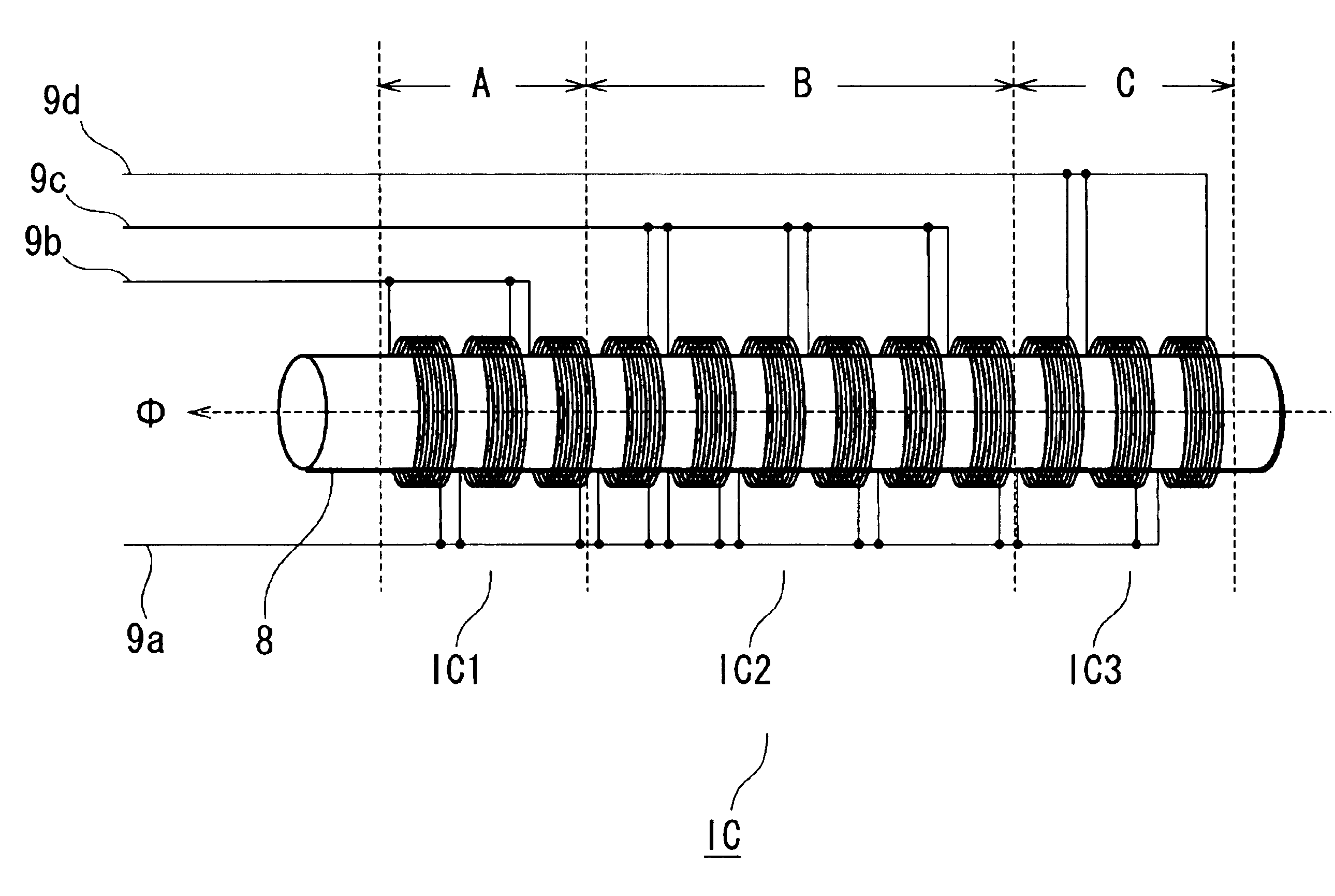
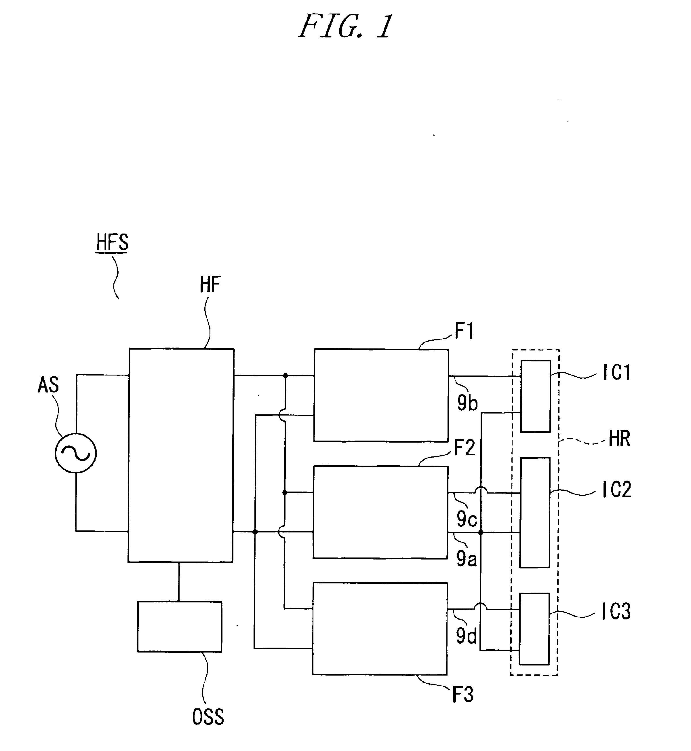
[0188]the induction heating roller apparatus according to the present invention will be described by referring to FIG. 18. This embodiment has the same circuit configuration as in FIG. 1. And of the four electric supply lines FC0, FC1, FC2 and FC3 in FIG. 1, the electric supply line FC0 is connected in common to one end of each of the three induction coils IC1, IC2 and IC3, and is also connected to the stable potential side of an output terminal of a high frequency power supply HFS via induction coil selection means F1, F2 and F3. The electric supply line FC1 is connected to the other end of the induction coils IC1. Likewise, the electric supply line FC2 is connected to the other end of the induction coil IC2, and FC3 is connected to the other end of the induction coil IC3 respectively.

[0189]As shown in FIG. 18, the coil bobbin CB has the four electric supply line accommodation grooves G0, G1, G2 and G3 placed with a 90-degree spacing on the outer face thereof. And the electric supp...

ninth embodiment

[0190]the induction heating roller apparatus according to the present invention will be described by referring to FIGS. 19 and 20. This embodiment has the induction coils IC placed on the outer face of the coil bobbin CB, and also has the pair of electric supply lines FC1, FC2 accommodated inside the coil bobbin CB. To be more specific, the coil bobbin CB has its bobbin constituting pieces CB1, CB2 forming a solid semi-cylinder and equipped with the electric supply line accommodation groove G on the juncture side respectively. In addition, the communicating hole H is communicated between the outer face of the coil bobbin CB and the electric supply line accommodation groove G.

[0191]When the bobbin constituting pieces CB1, CB2 are in a separate state, the electric supply lines FC1, FC2 fit the electric supply line accommodation groove G, and the tips of the connecting portions JC jut out of the communicating hole H to the outside.

[0192]The induction coils IC1, IC2 and IC3 are supporte...


PUM


Abstract

An induction heating roller apparatus has a heating roller for generating heat with an induction current by being magnetically coupled to an induction coil, and a plurality of induction coils placed in a dispersed state in an axial direction inside the heating roller and also set such that adjacent heating rollers are in mutually reversed winding directions so that generated flux has the same polarity. A high frequency power supply is provided for supplying high frequency power to the plurality of induction coils.

Description

BACKGROUND OF THE INVENTION[0001]1. Field of the Invention[0002]The present invention relates to an induction heating roller apparatus and to an image formation apparatus, which are provided with the fixing apparatus.[0003]2. Description of the Prior Art[0004]Heating rollers, which employ halogen lamps as heat sources, are used in the prior art to thermally fix a toner image. However, the halogen lamp heat sources are inefficient and require a large amount of power. Accordingly, a technique involving induction heating is being developed to solve such problems.[0005]Japanese Laid-Open Patent Publication No. 2000-215974 describes an exciting coil, which is arranged near a heated object. The exciting coil generates an induction current in the heated object, which is a magnetic heating roller. The exciting coil is formed by winding a coil in a planar manner along a curved surface of the heated object. A magnetic core is arranged along the curved surface or the exciting coil on the side ...

Claims


Application Information

Patent Timeline
IPC IPC(8): H05B6/14
CPCH05B6/145G03G15/2042G03G15/2053
Inventor TANAKA, TAKAAKISUZUKI, TOSHIYAOGASAWARA, TAKAYUKIYOKOZEKI, ICHIROKIKA, MANABU
Owner HARISON TOSHIBA LIGHTING CORP
Why Eureka
Try Eureka