Permanent magnet rotor and magnet cradle

a permanent magnet rotor and magnet cradle technology, which is applied in the direction of magnetic circuit rotating parts, dynamo-electric machines, etc., can solve the problems of interference with other parts, high speed/high power permanent magnet motor design, and limited speed and power of permanent magnet motors or alternators with magnets mounted with this first approach

Active Publication Date: 2005-08-23
ELLIOTT CO
View PDF7 Cites 65 Cited by
  • Summary
  • Abstract
  • Description
  • Claims
  • Application Information

AI Technical Summary

Benefits of technology

[0009]A plurality of non-magnetic cradles supports the permanent magnets in the recessed slots. Each cradle has a top and bottom wall abutting the top and bottom edge faces of the individual sections of the laminated permanent magnets. Each cradle has axial end walls with faces lying in planes perpendicular to the axis of rotation and w

Problems solved by technology

One of the challenges in designing high-speed permanent magnet motors is retention of the magnets on the rotor shaft during high-speed operation.
Since the centrifugal force is proportional to the radius at the center of mass of the magnet and the square of the angular speed, high speed/high power permanent magnet motor designs are difficult.
The speed and power of p

Method used


Image

  • Permanent magnet rotor and magnet cradle
  • Permanent magnet rotor and magnet cradle
  • Permanent magnet rotor and magnet cradle

Examples


Embodiment Construction

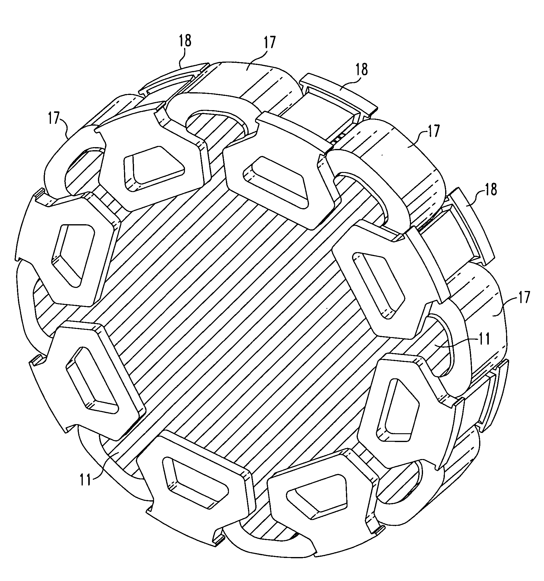
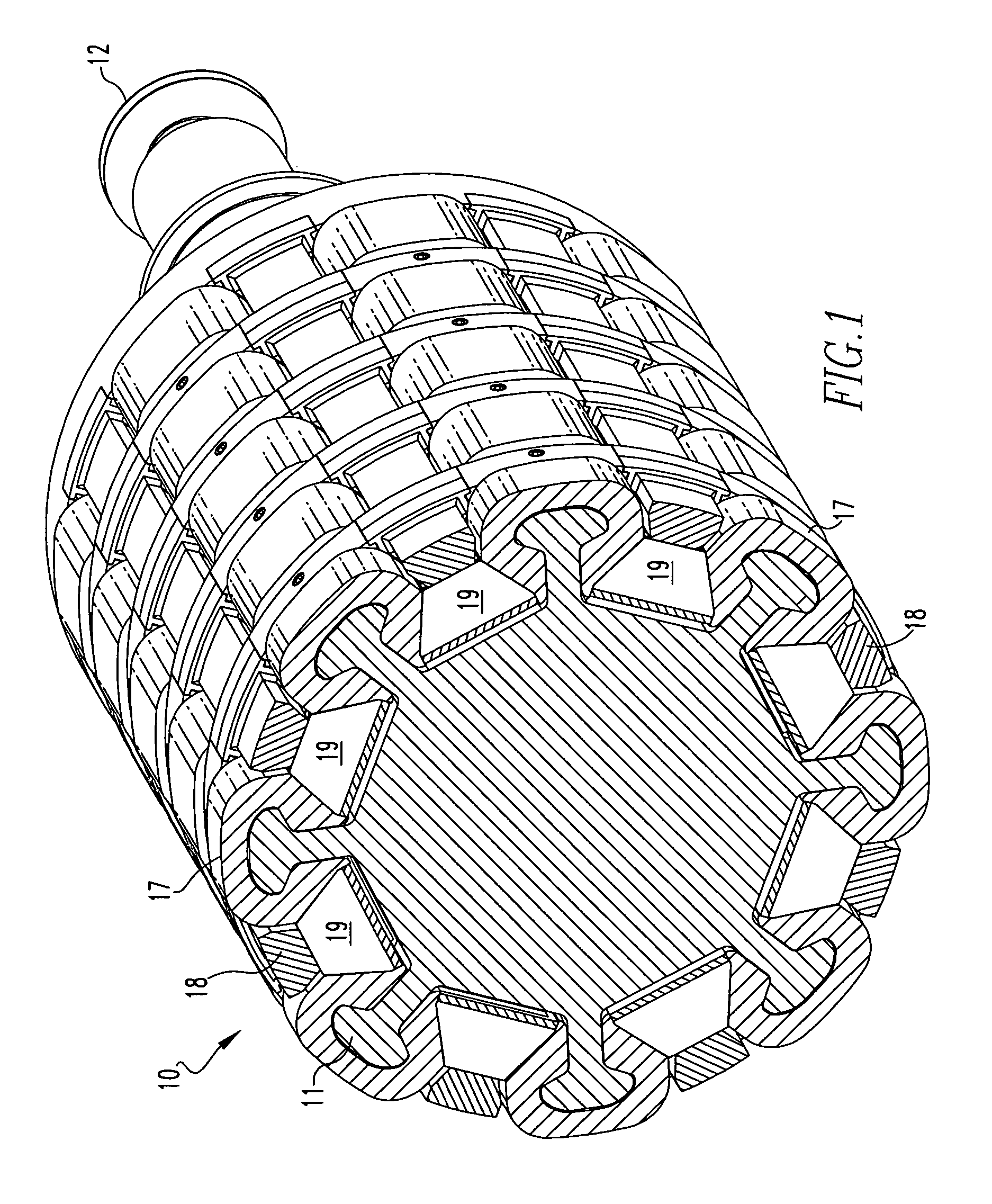
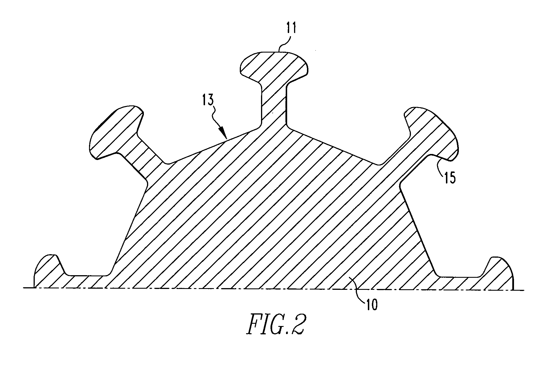
[0021]Referring to FIG. 1, the shaft 10 comprises the foundation of the permanent magnet rotor according to this invention. The shaft 10 is made of non-magnetic high strength material, such a nickel cobalt alloy. As shown in FIG. 2, the shaft 10 has an interrupted cylindrical surface defined relative to the rotational axis of the rotor. At each end of the shaft, provisions are made for bearings 12. The bearings 12 establish the rotational axis of the rotor. The shaft 10 has an even number of substantially identical recessed and overhung slots 13. The slots 13 define substantially identical generally T-shaped ribs 11 with dovetail surfaces 15 adjacent the slots. The magnets, as will be explained, are positioned within the slots held by a cradle.

[0022]While the shaft 10 has a continuous cross section (extending axially) in the vicinity of the magnets, it is helpful to consider the shaft in individual sections supporting an even number of magnets. FIG. 3 illustrates such a section brok...


PUM


Abstract

A magnet cradle for supporting a permanent magnet in an overhung recessed slot on the surface of a permanent magnet rotor having an axis of rotation. The cradle is non-magnetic and comprises a top and bottom wall abutting the permanent magnet. The cradle is sized to hold the permanent magnet within the overhung slots. Axial end walls generally perpendicular to the axis of rotation have circumferential edges configured to directly abut overhung portions of the slots. The total axial length of the top and bottom walls of the cradles in the axial direction are greater that the total axial length of the magnet, thereby permitting a magnet to fit between the axial end walls of the cradle without the cradle in the magnetic flux path of the magnet.

Description

BACKGROUND OF THE INVENTION[0001]One of the challenges in designing high-speed permanent magnet motors is retention of the magnets on the rotor shaft during high-speed operation. Centrifugal force due to rotation of the rotor causes the magnets to exert an outward (radial) force that must be mechanically restrained by the shaft. Since the centrifugal force is proportional to the radius at the center of mass of the magnet and the square of the angular speed, high speed / high power permanent magnet motor designs are difficult.[0002]Permanent magnet motors and alternators use two approaches to mount magnets to the rotor shaft. The first is called surface mounting wherein adhesives are used to bond the magnets to the surface of the rotor shaft. In many designs, the magnets are additionally retained by strapping high-strength, non-metallic bands around the rotor shaft over the magnets. See, for example, Johnson et al. U.S. Pat. No. 5,801,470 entitled “Rotors with Retaining Cylinders and R...

Claims


Application Information

Patent Timeline
IPC IPC(8): H02K1/27
CPCH02K1/2773
Inventor WATSON, ANDREW P.
Owner ELLIOTT CO
Why Eureka
Try Eureka