
Multifrequency electro-magnetic field generator

a generator and electromagnetic field technology, applied in the field of electromagnetic field generators, can solve the problems of limiting the effect of users, affecting the application of electro-magnetic fields on users, and inability to generate field flux lines that extend substantially beyond the generator in shape, size and direction, so as to achieve the effect of minimizing the generation of electric fields

Active Publication Date: 2005-08-23
KOONCE GENE
View PDF2 Cites 9 Cited by
  • Summary
  • Abstract
  • Description
  • Claims
  • Application Information

AI Technical Summary

Benefits of technology

[0007]The present invention overcomes the disadvantages and limitations of the prior art by providing a device which is capable of generating multifrequency electro-magnetic fields that project sufficiently to adequately engage a user and have a desired shape, size and direction. In addition, embodiments of the present invention substantially eliminate electric fields that emanate from the multifrequency electro-magnetic field generator.
[0010]The advantages of the present invention are that multifrequency electro-magnetic fields can be generated that project substantially from the electro-magnetic field generator to engage users. In addition, the generation of electric fields is minimized due to the use of certain materials in the device.

Problems solved by technology

A particular problem associated with these types of electro-magnetic field generators is that they are incapable of generating field flux lines that extend substantially beyond the generator in a shape, size and direction to adequately engage users of the device to create desired effects.
In other words, the direction and flow of flux lines created by prior art devices lacks sufficient curvature to project sufficiently from the device, which limits the effect on users.
Further, prior art devices are known to create electric fields in addition to electro-magnetic fields which negatively affect the application of the electro-magnetic fields on the user.

Method used


Image

  • Multifrequency electro-magnetic field generator
  • Multifrequency electro-magnetic field generator
  • Multifrequency electro-magnetic field generator

Examples


Embodiment Construction

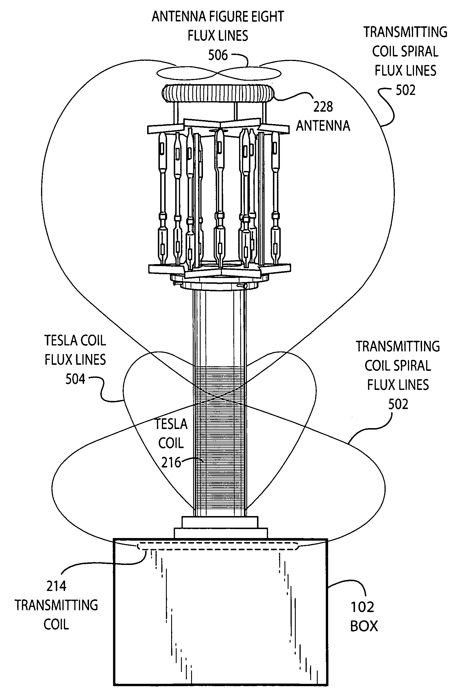
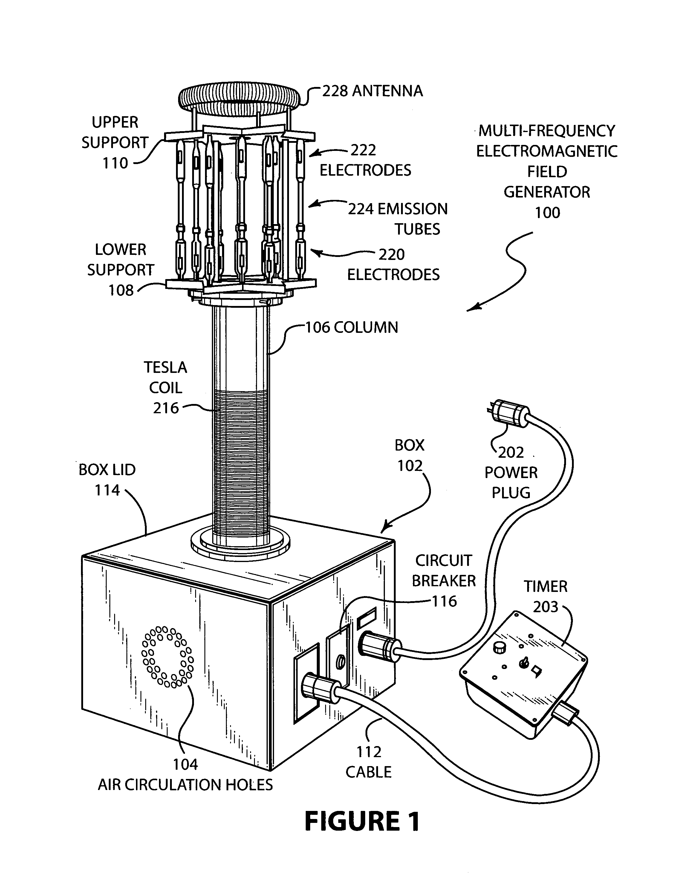
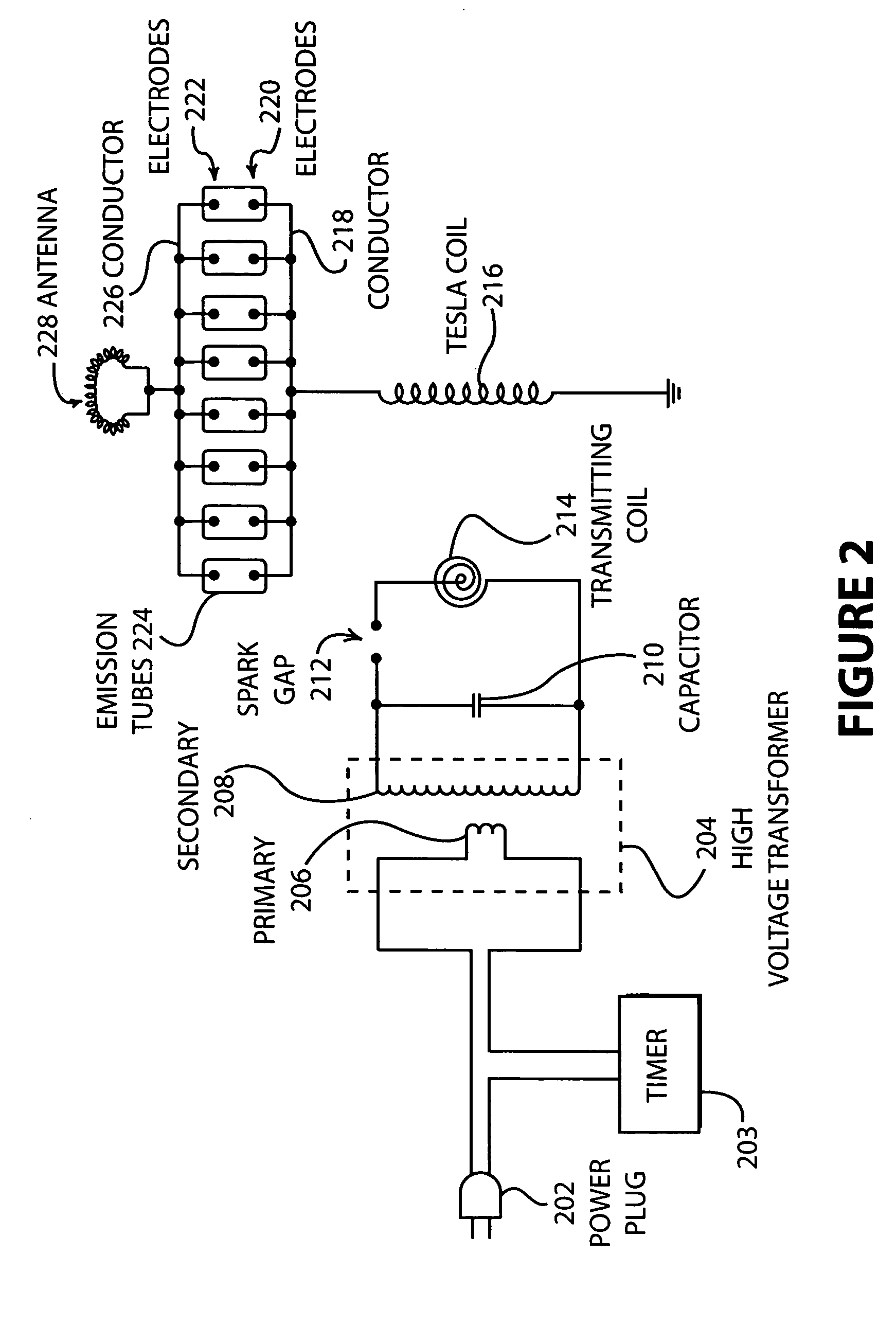
[0017]FIG. 1 is an isometric view of one embodiment of a multifrequency electro-magnetic field generator 100. As shown in FIG. 1, box 102 contains various electronics. Box 102 may be made from a material such as Bakelite or Phenolic and can take any shape. This material substantially restricts the emanation of electric fields that are generated by the electrical devices contained within box 102. Of course, any type of materials can be used to shield the electric field radiation including foils, screens, faraday cages, etc. Air circulation holes 104 provide air circulation to the interior of the box where the electronics are located. Fans may be provided to increase the airflow, which may be located within the box 102. Mounted on the top of the box 102 is a column 106. The column 106 is attached to a lower support 108. Disposed between the lower support 108 and upper support 110 are a series of emission tubes 224. Each of the emission tubes 224 has electrodes 220 located on the botto...


PUM


Abstract

Disclosed is a multifrequency electro-magnetic field generator that is capable of generating electro-magnetic flux fields that are projected at a distance from the device. Radial fields, horizontal fields and spiral fields are generated by the electro-magnetic field generator and are projected at a distance sufficient to engage a user of the device. A wide range of frequencies is generated as a result of the fast rise time pulses produced by the device. The geometry and structure of the device cause the electro-magnetic fields to encircle the device and be collected at the far end of the device by an antenna. This geometry and structure aid in the projection of the electro-magnetic fields.

Description

CROSS REFERENCE TO RELATED APPLICATIONS[0001]The present application is based upon and claims the benefit of U.S. Provisional Patent Application Ser. No. 60 / 515,904 by Gene Koonce, entitled “Multifrequency Electro-magnetic Field Generator” filed Oct. 29, 2003, the entire contents of which is hereby specifically incorporated by reference for all it discloses and teaches.BACKGROUND OF THE INVENTION[0002]a. Field of the Invention[0003]The present invention pertains generally to electro-magnetic field generators and more particularly to multifrequency electro-magnetic field generators.[0004]b. Description of the Background[0005]Various types of electro-magnetic field generators have existed. For example, U.S. Pat. Nos. 5,908,444 and 6,217,604 describe electro-magnetic field generators that are capable of generating multiple frequencies. These patents are specifically incorporated herein, by reference, for all that they disclose and teach. A particular problem associated with these types...

Claims


Application Information

Patent Timeline
IPC IPC(8): A61N5/00
CPCA61N5/00
Inventor KOONCE, GENE
Owner KOONCE GENE
Learn More