
Trailer based collision warning system and method

a collision warning and trailer technology, applied in the field of sensor based systems, can solve the problems of large trucks with significant blind spots, poor visibility for drivers, and large vehicle types with large differences in size, and achieve the effect of low cost and portability

Inactive Publication Date: 2005-08-23
ALTRA TECH
View PDF87 Cites 241 Cited by
  • Summary
  • Abstract
  • Description
  • Claims
  • Application Information

AI Technical Summary

Benefits of technology

[0014]In another embodiment of the present invention, a portable audio receiver is adapted to receive audio signals superimposed on the battery wire. The portable audio receiver is further adapted for use with a tractor cigarette lighter outlet or vehicle auxiliary power outlet, generally associated with the tractor pulling the trailer. The low cost and portability of the portable audio receiver make it practical to provide for each tractor hired to pull the trailer.

Problems solved by technology

Two particular problems in maintaining safety is the size differentials among the wide variety of vehicle types and the poor visibility drivers experience due to the inherent design of the larger vehicles.
Large trucks have significant blind spots in which they cannot see other vehicles.
Regardless, accidents often occur during the operation of large trucks on rural and urban roads.
This system is limited in that it is designed for single chassis vehicles up to and including commercial straight trucks.
It does not address the needs of combination tractor trailer rigs and does not provide any side collision warning capability.
This system has limitations in that it is limited to a maximum of seven sensors and the tractor and trailer both need to be equipped with the Transportation Safety Technologies product.
If the tractor is so equipped and the trailer is not, the system is limited to monitor the blind spots on the sides of the tractor with no protection around the trailer.
If the trailer is equipped with this system and the tractor is not, the trailer sensors are useless since they rely on the Driver Alert Module in the tractor of the combination tractor-trailer rig.
The combination tractor-trailer rig presents a unique set of problems not previously addressed by manufacturers of collision warning systems.
These problems include the following: (a) previous collision warning systems required electronic devices and feedback mechanisms to be installed on or in the tractor, (b) the company that provides the tractor is often different from the company that owns the trailer, (c) there are three times as many trailers in the marketplace as there are tractors, and (d) one tractor may pull many different trailers during the course of a day, week, month, or year.
In cases where a trailer fleet owner is interested in implementing collision warning on their trailers, they can't be assured that the independent owner-operators that they hire to pull the company's trailers will be using tractors equipped with a collision warning system.
However, truck drivers often use the engine and transmission to slow down the vehicle without activation of the brakes.
Tandem trailers (i.e. two trailers pulled behind a single tractor) also present a unique set of problems.
To-date there has not been a collision warning solution for tandem-trailers.
Since the rear of trailers, and to a lesser extent the sides of the trailer, present a major blind spot to the driver, improvements in combination tractor-trailer safety will be limited unless a means is found to provide automatic hazard detection and collision warning on the trailer independent of the tractor pulling the trailer and to provide a means of communicating visual alarms, audible alarms, and video information to the driver.
Another trailer issue that requires attention is the theft of goods and the hijacking of trailers.

Method used


Image

  • Trailer based collision warning system and method
  • Trailer based collision warning system and method
  • Trailer based collision warning system and method

Examples


Embodiment Construction

[0039]In the following detailed description of the preferred embodiments, reference is made to the accompanying drawings, which form a part hereof, and in which is shown by way of illustration specific preferred embodiments in which the invention may be practiced. In the drawings, like numerals describe substantially similar components throughout the several views. These embodiments are described in sufficient detail to enable those skilled in the art to practice the invention, and it is to be understood that other embodiments may be utilized and that logical, mechanical and electrical changes may be made without departing from the spirit and scope of the present inventions. The following detailed description is, therefore, not to be taken in a limiting sense, and the scope of the present invention is defined only by the appended claims and their equivalents.

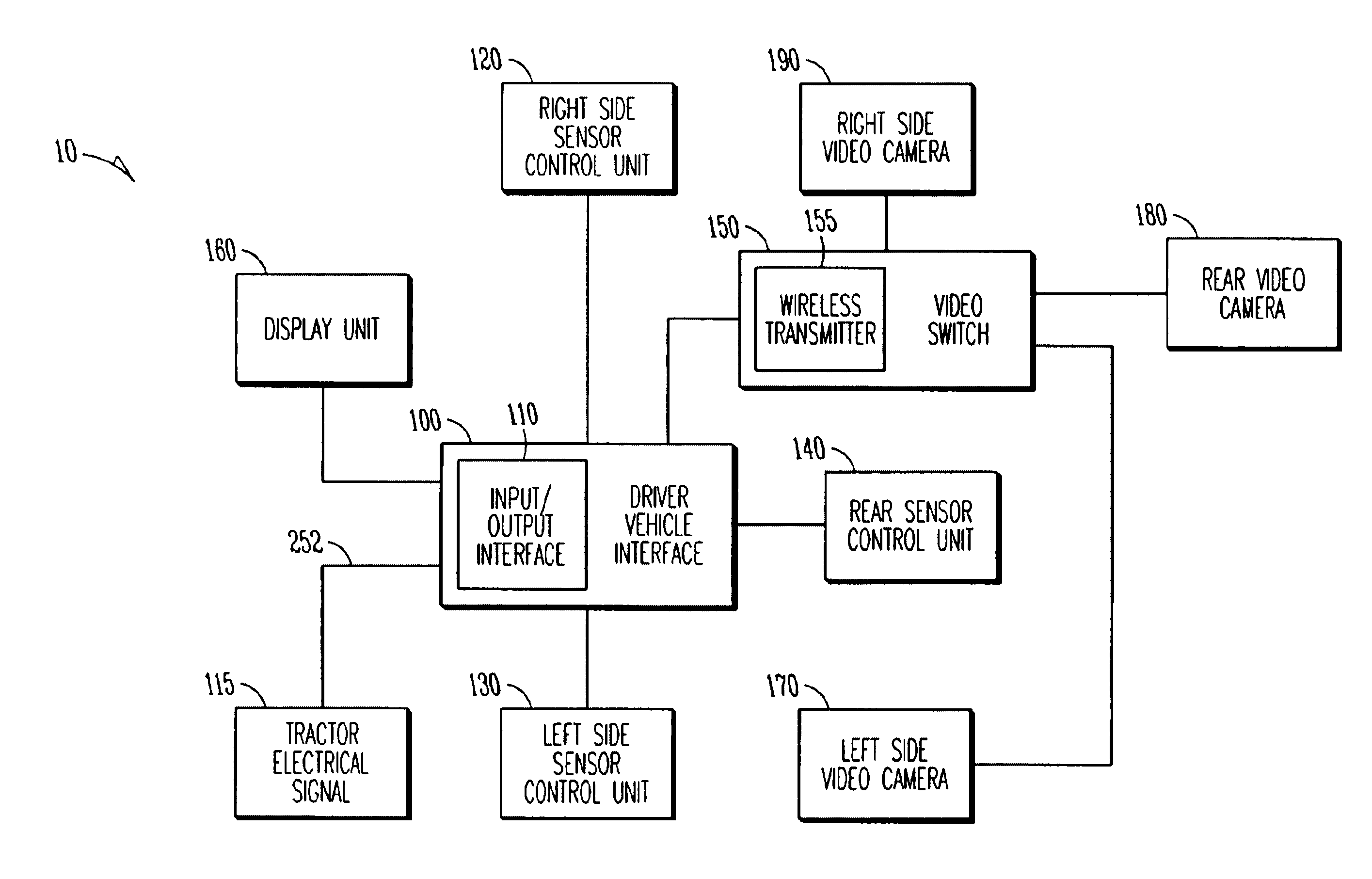
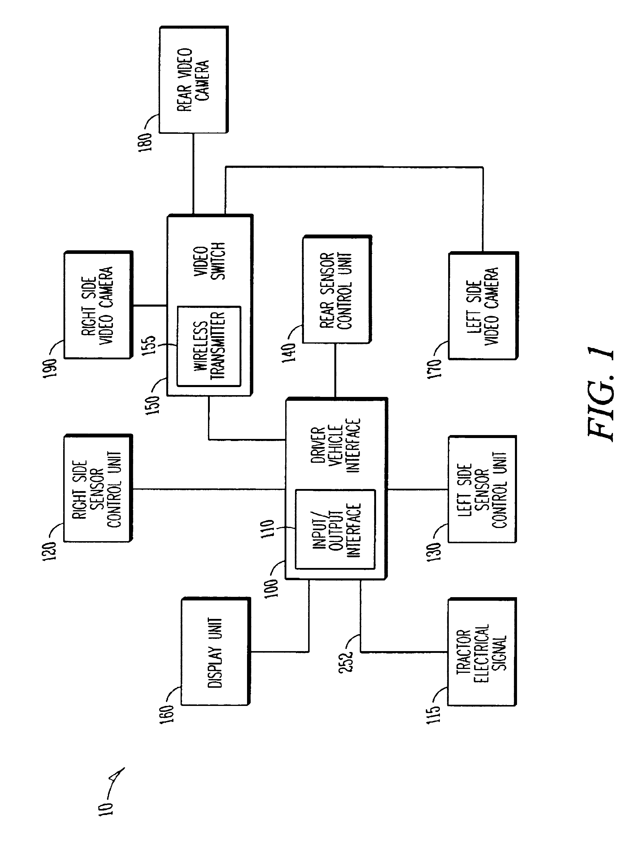
[0040]FIG. 1 shows a block diagram for the functional units of a trailer based collision warning system 10. In an embodiment o...


PUM


Abstract

A trailer based collision warning system includes one or more side object detection sensors, one or more backup assist sensors, a driver vehicle interface, and trailer-mounted display units operating essentially independent of the tractor with all detection and warning system equipment mounted on the trailer. The trailer based collision warning system is coupled to industry-standard tractor to trailer wiring to provide the trailer with power and signals such as left turn indication and right turn indication. The side and rear sensors detect the presence and location of objects and transfer this information to a driver vehicle interface device located on the trailer. The system can also be equipped with video cameras with a means of automatically activating the camera in the area where a hazard condition has been detected. The driver vehicle interface determines the nature of the information and / or warning needed by the driver and provides this information in the form of signals sent to displays that can to assist the driver in safely maneuvering the trailer. The collision warning system can also operate in a security mode.

Description

TECHNICAL FIELD OF THE INVENTION[0001]The present invention relates generally to sensor based systems, and more particularly to a vehicle mounted collision avoidance system, which warns drivers of potential collisions.BACKGROUND OF THE INVENTION[0002]High traffic loads fill today's roads and highways with a wide variety of vehicle types. Maintaining vehicle safety on these roads is of paramount importance. Two particular problems in maintaining safety is the size differentials among the wide variety of vehicle types and the poor visibility drivers experience due to the inherent design of the larger vehicles. Motorcycles and passenger vehicles are much smaller than the trucks that use the same roads. Large trucks have significant blind spots in which they cannot see other vehicles. Attempts have been made to educate the public on the NO-ZONE of blinds spots around a large truck. Regardless, accidents often occur during the operation of large trucks on rural and urban roads. Providing...

Claims


Application Information

Patent Timeline
Patent Type & Authority Patents(United States)
IPC IPC(8): B60R21/01B60R21/00B60R21/0134
CPCB60R21/013B60R21/0134B60R2021/0069B60Q9/008
Inventor GUNDERSON, RICHARD A.THIEDE, DAVID
Owner ALTRA TECH
Learn More