
Reconstruction of color components in digital image processing

a color component and digital image technology, applied in the field of color reconstruction, can solve the problem of inadequate polynomial reconstruction, and achieve the effect of reducing the impact of nois

Inactive Publication Date: 2005-08-23
KWE INT
View PDF16 Cites 19 Cited by
  • Summary
  • Abstract
  • Description
  • Claims
  • Application Information

AI Technical Summary

Benefits of technology

[0016]In some embodiments, the weights are chosen to reduce the impact of noise. In some embodiments, the reconstructed value of a color component is adjusted to incorporate information on color spikes that is carried by another color component.

Problems solved by technology

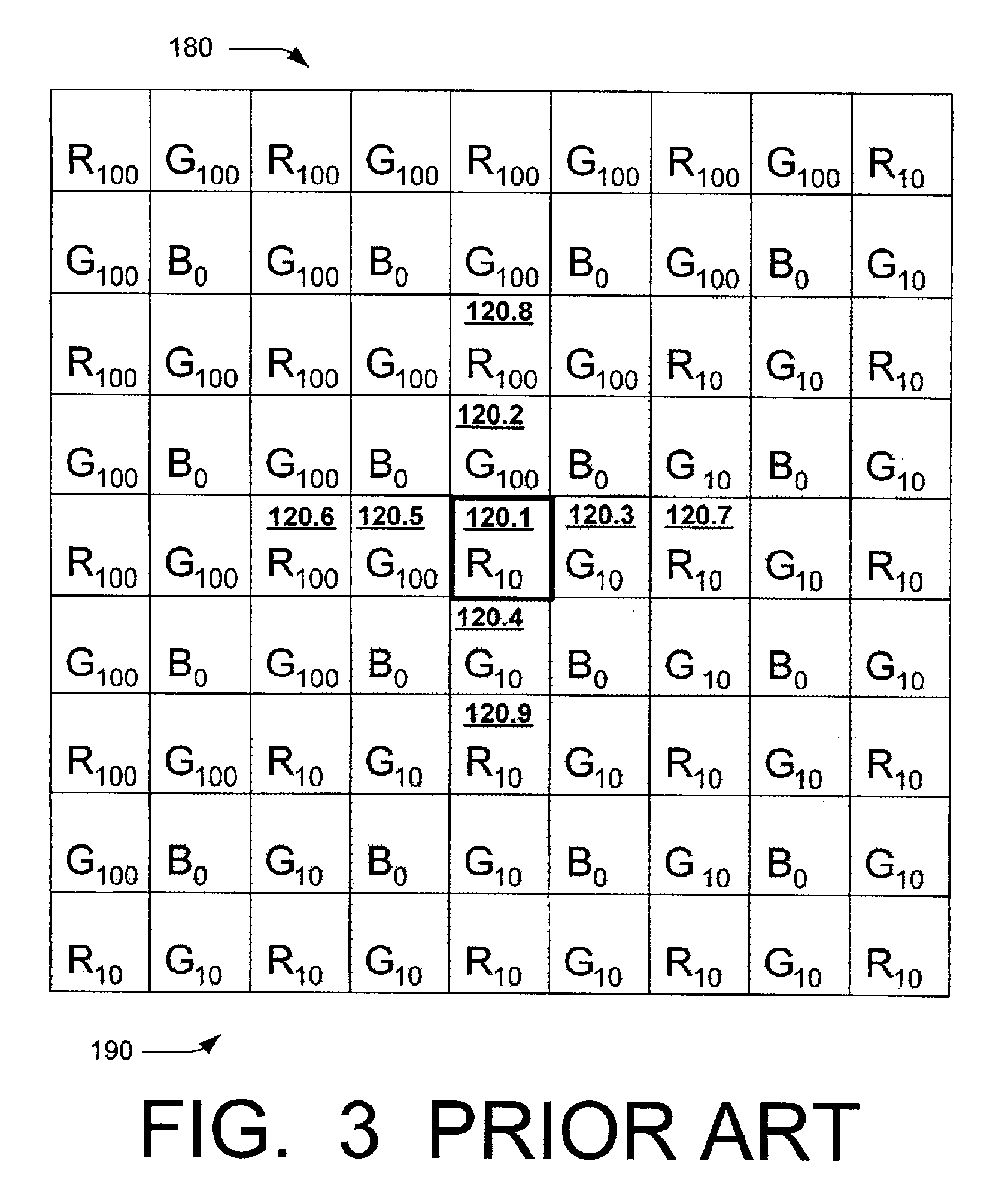
However, in regions of abrupt color transition the polynomial reconstruction is not adequate.

Method used


Image

  • Reconstruction of color components in digital image processing
  • Reconstruction of color components in digital image processing
  • Reconstruction of color components in digital image processing

Examples


Embodiment Construction

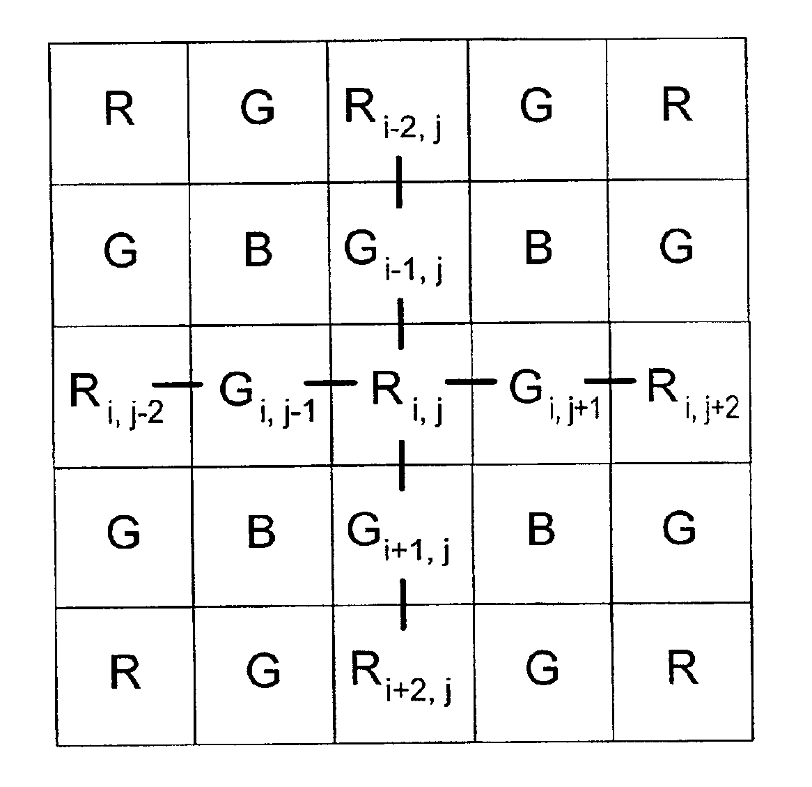
[0024]Color reconstruction using weights will now be illustrated for one embodiment using a Bayer color filter array. The array is illustrated in FIG. 4. The pixels are indexed for ease of reference by numbers i, j, where i is the row number and j is the column number. Ri,j indicates the red intensity at pixel (i, j), Gi,j−1 indicates the green intensity at pixel (i, j−1), and so on. FIG. 4 illustrates actually measured (not reconstructed) intensities. The color reconstruction can be performed in the camera of FIG. 1 by a novel circuit 118. The invention is not limited to digital cameras. The color reconstruction can be performed by a separate computer or another suitable device, known or to be invented.

[0025]The green intensity at the red pixel (i, j) is reconstructed using four gradients ΔL, ΔR, ΔA, ΔB corresponding to four respective directions—left (“L”), right (“R”), up (or above, “A”), and down (or below, “B”). These gradients can be any values indicative of the magnitude of t...


PUM


Abstract

In some embodiments of the invention, when a color component (e.g. red, green or blue) is reconstructed at a pixel from the intensity values for this component at adjacent pixels, the intensities at the adjacent pixels are assigned weights. Greater weights are assigned to those pixels for which a gradient is smaller. The gradient for each adjacent pixel is indicative of a magnitude of a change of another color component in the direction of the adjacent pixel and / or a magnitude of the rate of change of the other color component in the direction of the adjacent pixel. In some embodiments, the weights are chosen to reduce the impact of noise. In some embodiments, the reconstructed value of a color component is adjusted to incorporate information on color spikes that is carried by another color component.

Description

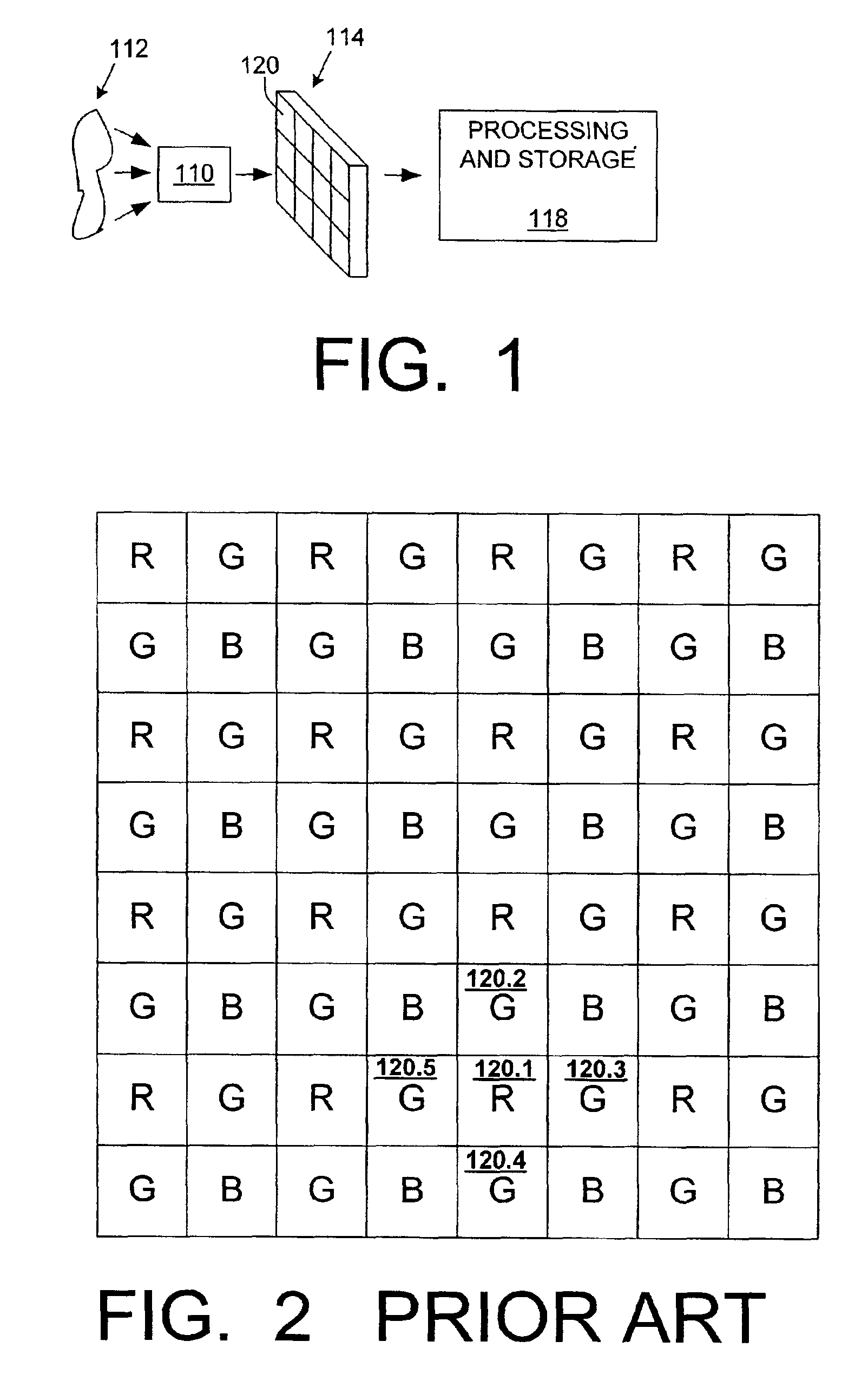
BACKGROUND OF THE INVENTION[0001]The present invention relates to digital image processing, and more particularly to color reconstruction. Some embodiments can be used to process images obtained by digital photographic or video cameras.[0002]FIG. 1 illustrates a digital camera. (FIG. 1 is not labeled “prior art” because it will also be used to illustrate some features of the present invention.) Optical system 110 causes an image of a scene 112 to appear on an electronic image-capturing device 114. Device 114 may be a charge coupled device (CCD), a CMOS (Complementary Metal Oxide Semiconductor) based device, or some other type. Device 114 contains an array of light sensors 120 (e.g. photodiodes). Each sensor generates an analog electrical signal indicative of the number of photons registered by the sensor.[0003]The analog signals are converted to digital signals by an A / D converter (not shown). The digital signals are processed by a circuit 118 as desired. Circuit 118 may also perfor...

Claims


Application Information

Patent Timeline
IPC IPC(8): G06T3/40H04N9/04H04N5/44
CPCG06T3/4015H04N7/0122H04N9/045H04N2209/046H04N23/843H04N25/134
Inventor BEZRYADIN, SERGEY N.
Owner KWE INT
Learn More