
Disk drive monitoring a supply current to protect motor driver circuits

a technology of driver circuits and monitors, which is applied in the direction of magnetic recording, data recording, instruments, etc., can solve the problems of increasing the cost and complexity affecting the performance of the disk drive, and affecting the reliability of the disk driv

Active Publication Date: 2005-08-23
WESTERN DIGITAL TECH INC
View PDF15 Cites 123 Cited by
  • Summary
  • Abstract
  • Description
  • Claims
  • Application Information

AI Technical Summary

Benefits of technology

The present invention is a disk drive with a voice coil motor for actuating the head over the disk. The drive also includes a spindle motor with windings that are selectively connected to the supply voltage to rotate the spindle. A current sensor generates a current sensory signal that represents the current flowing from the supply voltage. A current limit circuit compares the current sensory signal to a threshold and disconnects the windings and voice coil from the supply voltage if the current sensory signal exceeds the threshold. The invention also includes a spindle driver with switches for selectively connecting the windings to the supply voltage and ground, and a signal generator for generating a pulse width modulated signal to control the amount of current flowing through the windings. The technical effects of the invention include improved performance and efficiency of the disk drive.

Problems solved by technology

Excessive current due, for example, to a motor winding shorting to a ground source can damage the motor driver circuits.
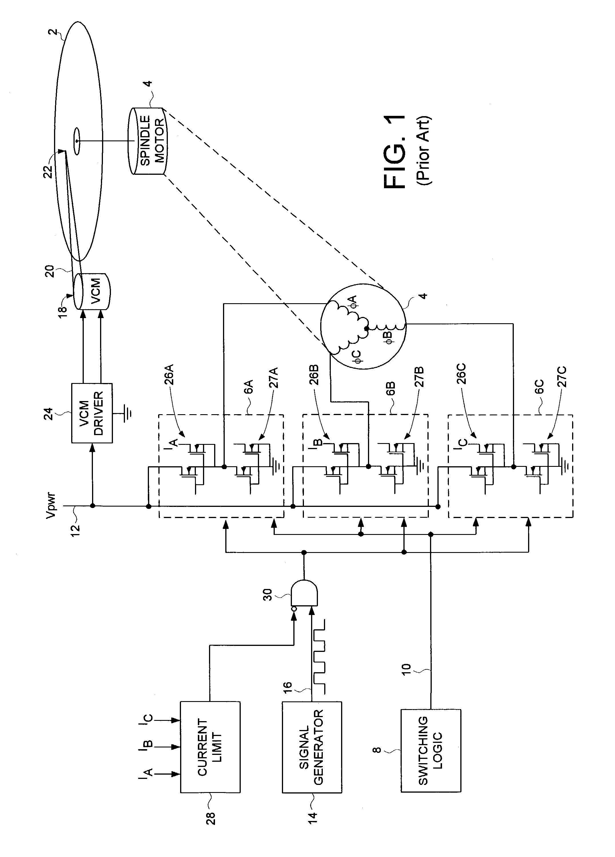
Although this technique helps protect the driver circuits of the spindle motor 4, the driver circuits of the VCM 18 remain susceptible to damage from excessive current.
This technique also increases the cost and complexity of the disk drive since it requires a separate current sensor for each pair of switches (6A, 6B, 6C) of the spindle motor 4.
Current sensors could also be employed to protect the driver circuits for the VCM 18 (similar to the current sensors (26A, 26B, 26C) that protect the driver circuits for the spindle motor 4); however, this solution would also increase the cost and complexity of the disk drive.

Method used


Image

  • Disk drive monitoring a supply current to protect motor driver circuits
  • Disk drive monitoring a supply current to protect motor driver circuits
  • Disk drive monitoring a supply current to protect motor driver circuits

Examples


Embodiment Construction

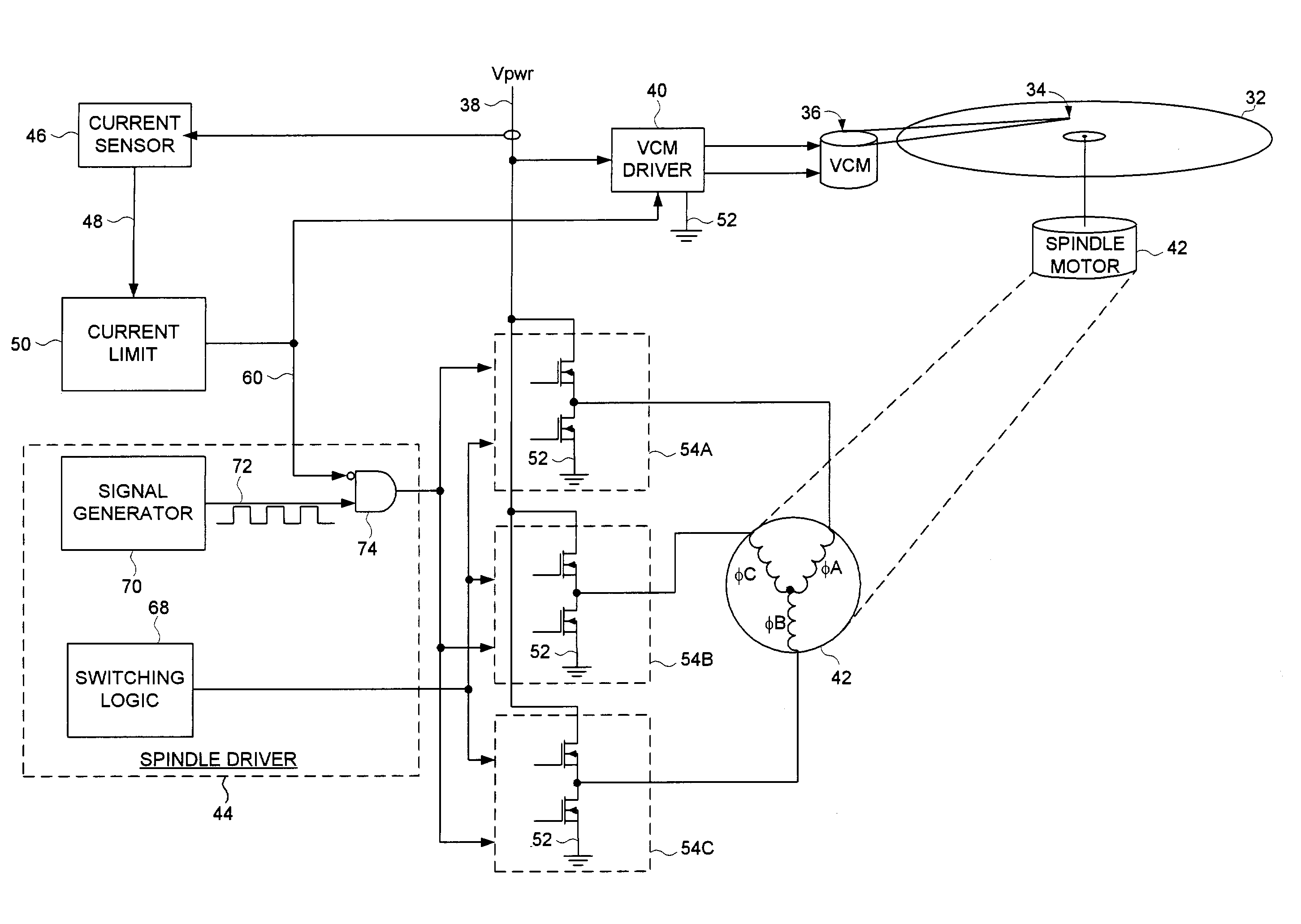
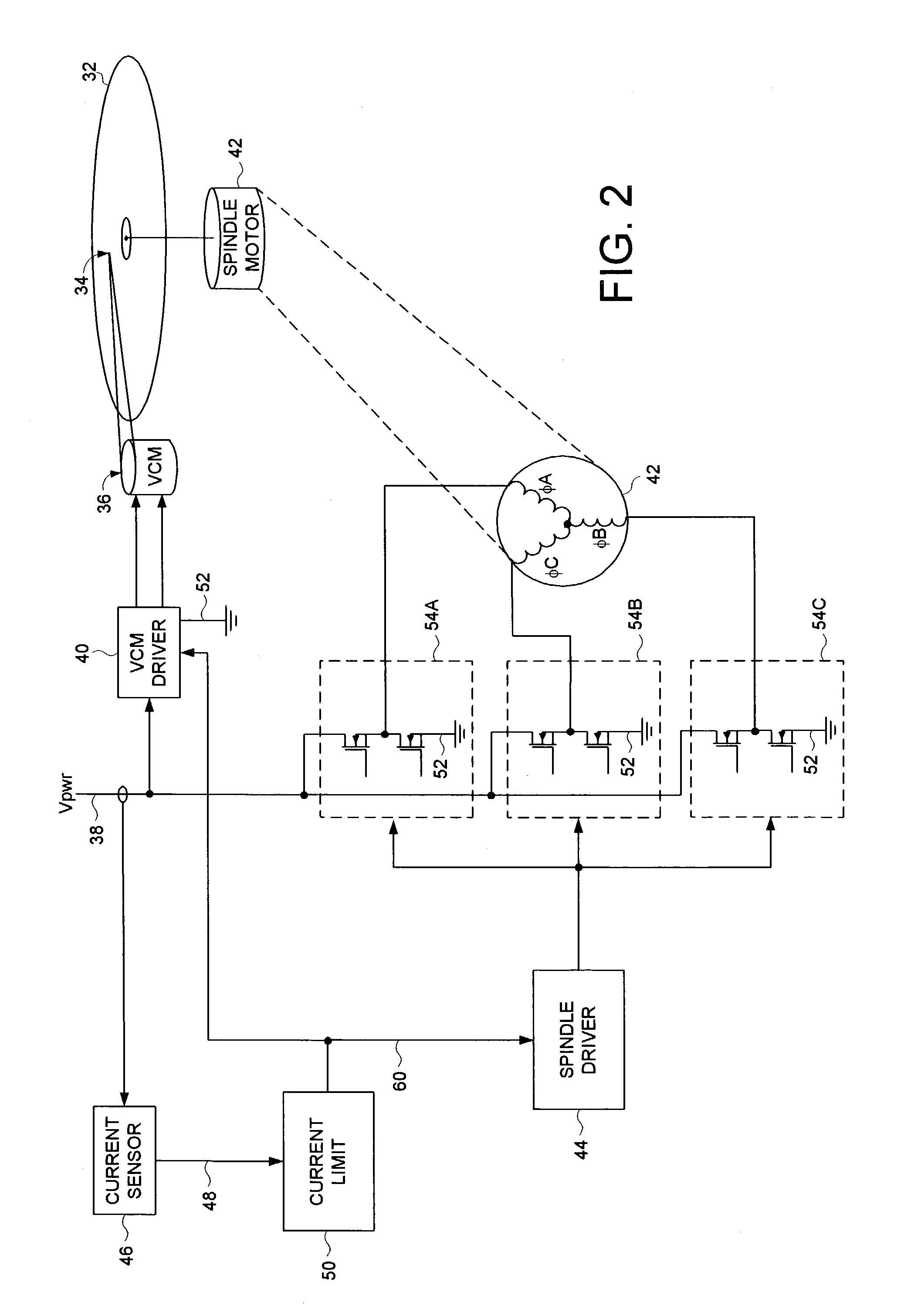
[0021]FIG. 2 shows a disk drive according to an embodiment of the present invention. The disk drive comprises a disk 32, a head 34, a voice coil motor (VCM) 36 for actuating the head 34 over the disk 32, the VCM 36 comprising a voice coil having a first end and a second end. The disk drive further comprises an interface for receiving a supply voltage 38 from a host computer. A VCM driver 40 connects the voice coil to the supply voltage 38 in order to actuate the head 34 over the disk 32. A spindle motor 42 rotates the disk 32, the spindle motor 42 comprising a plurality of windings (φA, φB, φC), wherein each winding comprises a first end and a second end. A spindle driver 44 selectively connects the windings to the supply voltage 38 according to a commutation sequence in order to rotate the spindle motor 42. A first current sensor 46 generates a current sense signal 48 representing a current flowing from the supply voltage 38, and a current limit circuit 50 compares the current sens...


PUM

PropertyMeasurementUnit
currentaaaaaaaaaa
currentaaaaaaaaaa
currentaaaaaaaaaa

Abstract

A disk drive is disclosed comprising a spindle motor for rotating a disk and a voice coil motor (VCM) for actuating a head over the disk. The spindle motor comprises a plurality of windings, and the VCM comprises a voice coil. If the current flowing from a supply voltage exceeds a threshold, the windings are disconnected from the supply voltage, the voice coil is disconnected from the supply voltage, and the first and second ends of the voice coil are connected to ground.

Description

BACKGROUND OF THE INVENTION[0001]1. Field of the Invention[0002]The present invention relates to disk drives for computer systems. More particularly, the present invention relates to a disk drive monitoring a supply current to protect motor driver circuits.[0003]2. Description of the Prior Art[0004]FIG. 1 shows a prior art disk drive comprising a disk 2 rotated about a center axis by a spindle motor 4. The spindle motor 4 comprises a number of windings (e.g., φA, φB, φC) configured to form a multi-phase motor. Each winding (φA, φB, φC) has a first end connected to a center tap and a second end connected to a respective pair of switches (6A, 6B, 6C). Switching logic 8 generates a control signal 10 for controlling the switches (6A, 6B, 6C) to selectively connect the second end of the windings to a supply voltage 12 or to ground according to a commutation sequence. A current flowing from the supply voltage 12 through the windings to ground generates a torque which causes the spindle mo...

Claims


Application Information

Patent Timeline
Patent Type & Authority Patents(United States)
IPC IPC(8): H02H5/00H02H5/04G11B19/04G11B19/20
CPCG11B19/04G11B19/20G11B5/40G11B5/553
Inventor RYAN, ROBERT P.
Owner WESTERN DIGITAL TECH INC
Learn More