Mount for use in optical fiber hydrophone array

a technology of hydrophone array and optical fiber, applied in the direction of optics, fibre mechanical structures, instruments, etc., can solve the problems of degrading light transmission, affecting the sound quality of the optical fiber, so as to avoid imparting or contributing to the increase of noise levels

Inactive Publication Date: 2005-08-23
GENERAL DYNAMICS MISSION SYST INC
View PDF82 Cites 88 Cited by
  • Summary
  • Abstract
  • Description
  • Claims
  • Application Information

AI Technical Summary

Benefits of technology

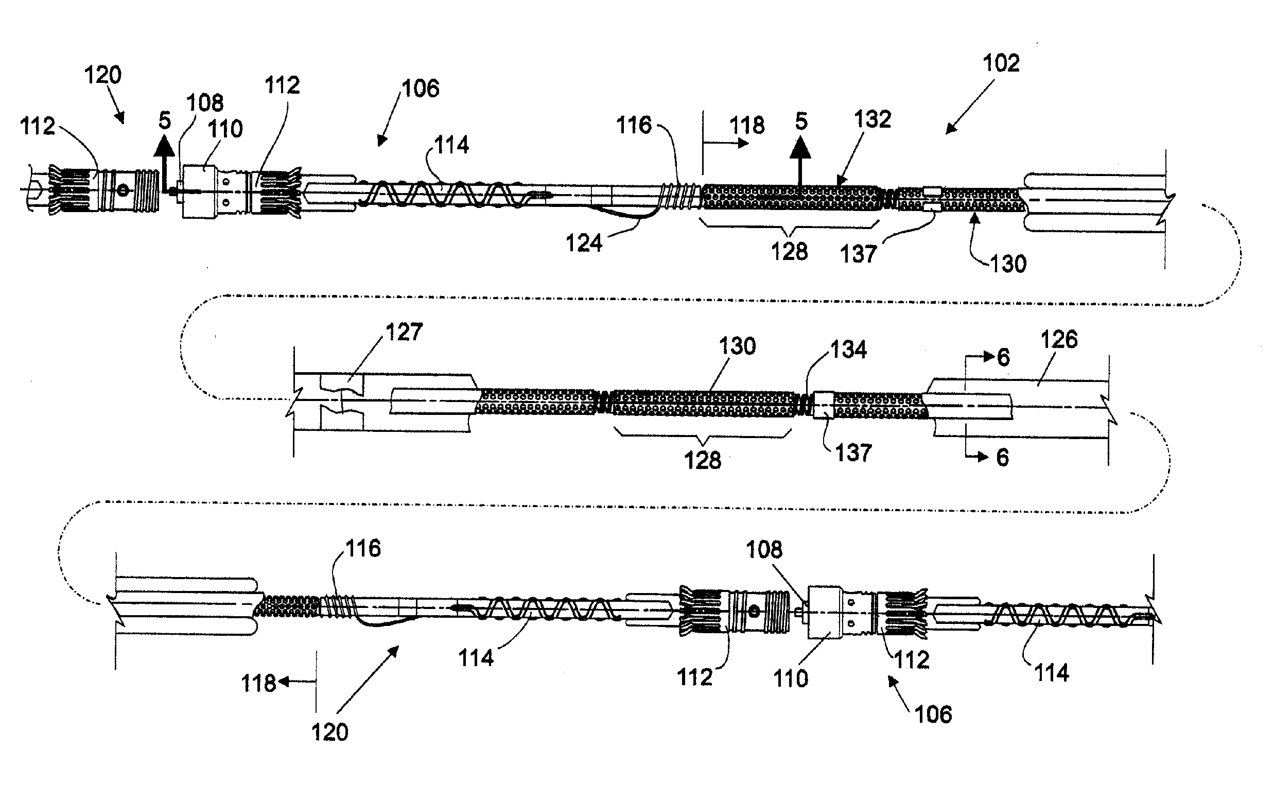
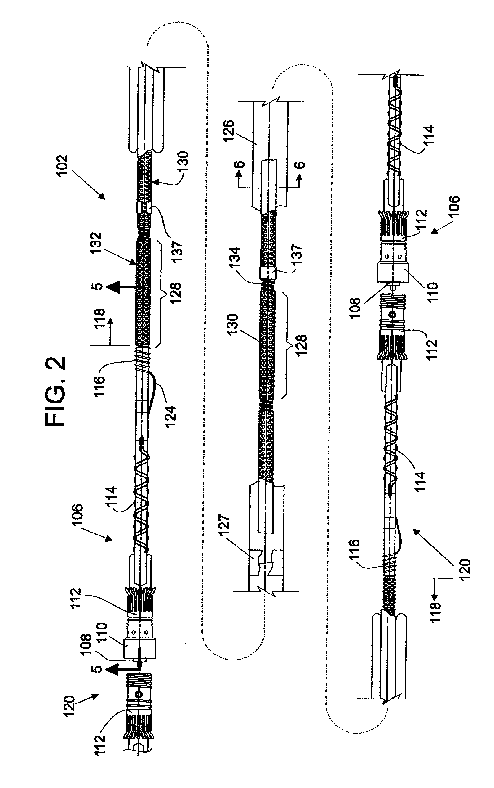
[0009]The present invention is for use in an optical hydrophone module, and more specifically, between the ends of modules. An optical hydrophone mount according to the present invention provides a structure that helps to avoid imparting or contributing to increased noise levels from components that surround and secure the hydrophone.

Problems solved by technology

While large bandwidth capabilities and small size make optical fibers desirable for use, optical fibers are mechanically fragile.
Tow-induced loads may cause the fibers to fracture.
Radial compressive loads may cause degraded light transmission as the result of a phenomenon known as microbending loss.
Stress corrosion is another cause of failure of optical fibers, and is a stress-accelerated chemical reaction between the optical fiber glass and water that can result in microcracks in the glass, adversely effecting fiber performance.
Optical fibers serving individual modules are limited in the number of light transmission channels available for communication with the monitoring equipment in the vessel.
Such connectors include fiber splice trays, which are commercially available, but are too large for retrofitting into thin-line towed sonar arrays.

Method used


Image

  • Mount for use in optical fiber hydrophone array
  • Mount for use in optical fiber hydrophone array
  • Mount for use in optical fiber hydrophone array

Examples


Embodiment Construction

[0058]Certain terminology is used herein for convenience only and is not to be taken as a limitation on the invention. For example, words such as forward, aft, upper, lower, left, right, horizontal, vertical, upward, and downward merely describe the configuration shown in the Figures. The components may be oriented in any direction and the terminology, therefore, should be understood as encompassing such variations unless specified otherwise. Also, the scope of the invention is not intended to be limited by the materials or dimensions listed herein, but may be carried out using any materials and dimensions that allow the construction and operation of the hydrophone module.

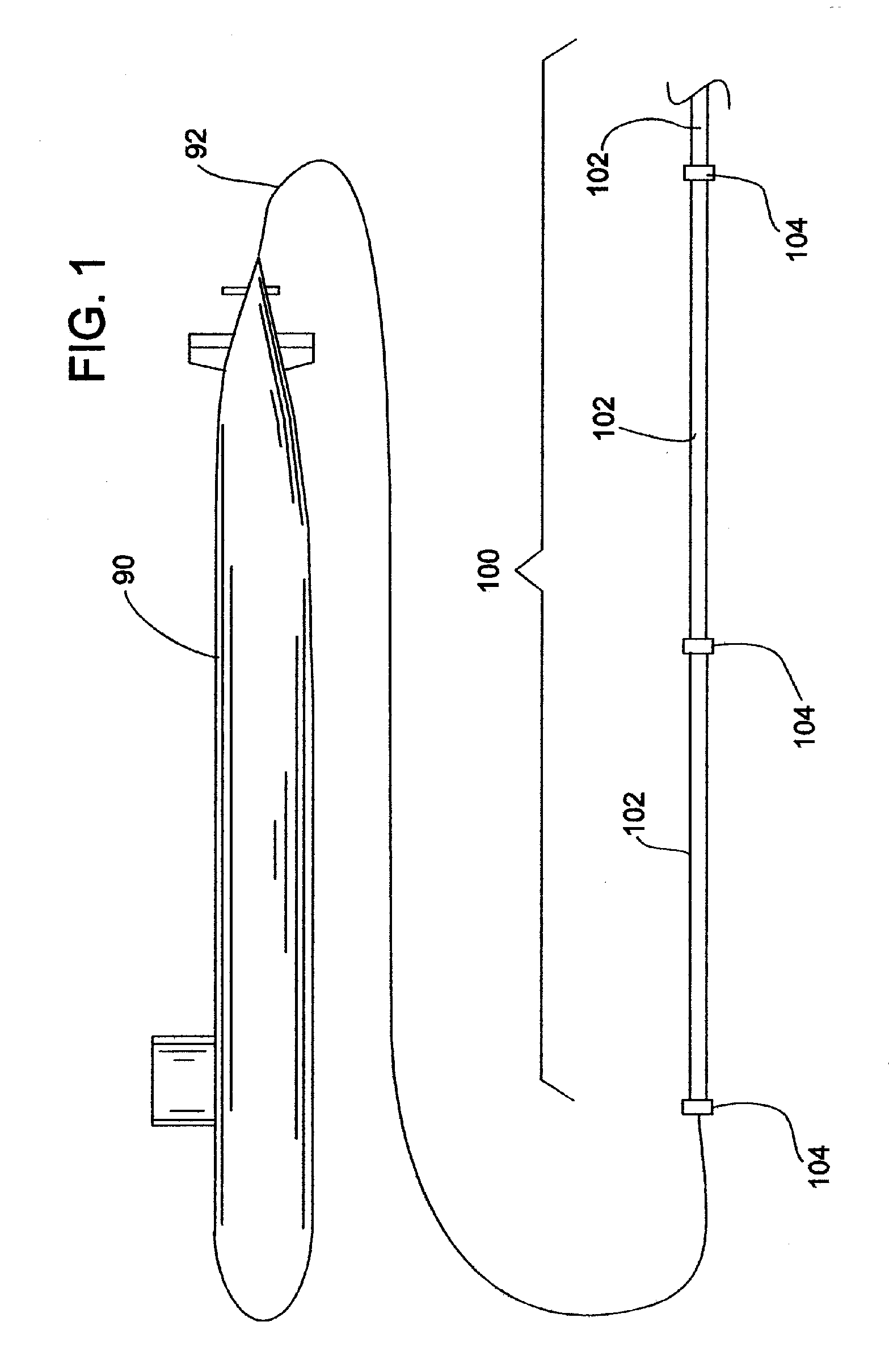
[0059]Referring now to the drawings, wherein like reference numerals illustrate corresponding or similar elements throughout the several views, there is shown in FIG. 1 a submarine 90 using a tow cable 92 to tow an optical hydrophone sonar array 100. The hydrophone array 100 is a linear array of modules 102 connect...


PUM


Abstract

A mount for use in an optical fiber hydrophone module to loosely secure hydrophone components while avoiding increasing noise to the hydrophone. A hydrophone core has a plurality of mandrels helically wrapped with optical fiber and connected along an axis. A cylindrical metal cage encircles the hydrophone core. Cloth tape is wrapped around and affixed to the metal cage. An open pore foam goes around the metal cage. Thermoplastic adhesive attaches the foam to the cloth tape. A cylindrical woven internal strength member goes around the foam, including two longitudinal positioning tapes. The positioning tapes are fastened to the member at each end, and the foam is between the positioning tapes. Thread is used to sew the positioning tapes to the foam at spaced intervals along the axis.

Description

FEDERAL RESEARCH STATEMENT[0001]This invention was made with Government support under Contract N00024-98-C-6308. The Government has certain rights in this invention.BACKGROUND OF INVENTION[0002]The science of underwater sonar equipment is increasingly relying on the use of fiber-optic technology. This reliance is driven by the requirement to have more acoustic sensors per sonar system, with higher sensitivities and lower cost.[0003]Passive sonar arrays towed from submarines or surface ships are excellent candidates for fiber-optic sensor technology. In this area, an all optical fiber hydrophone assembly is a recent development by the United States Naval Research Laboratories. The hydrophone assembly consists of a series of air-backed plastic cylinders, called mandrels, which are helically wrapped with optical sensing fiber. The hydrophone senses sound pressure levels through the strain induced in the optical sensing fiber as the sound pressure wave deforms the mandrel. Strain is imp...

Claims


Application Information

Patent Timeline
Patent Type & Authority Patents(United States)
IPC IPC(8): G02B6/44
CPCG02B6/4428
Inventor COOKE, DONALD A.MCGOVERN, KENNETH M.
Owner GENERAL DYNAMICS MISSION SYST INC
Why Eureka
Try Eureka