Power transmission device

Inactive Publication Date: 2011-02-24
TOYOTA JIDOSHA KK
View PDF7 Cites 17 Cited by
  • Summary
  • Abstract
  • Description
  • Claims
  • Application Information

AI Technical Summary

Benefits of technology

[0011]The power transmission device according to the present invention in operation can reduce the agitation

Problems solved by technology

Therefore, it takes some time for the oil pumped up by an oil pump to return to the bottom p

Method used


Image

  • Power transmission device
  • Power transmission device
  • Power transmission device

Examples


Embodiment Construction

[0022]A power transmission device according to an embodiment of the present invention will be described with reference to FIGS. 1 to 10. It should be noted that, where any number, quantity or the like is referred to in the embodiments described below, the scope of the present invention is not necessarily limited to the number, quantity or the like unless otherwise specified. Further, each element in the following embodiments is not necessarily requisite for the present invention unless otherwise specified. Furthermore, where a plurality of embodiments are illustrated below, it is originally intended that respective features of the embodiments may be combined as appropriate. A power transmission device in the present embodiment refers to an automatic transmission for an automobile. The automobile in the present embodiment refers to an FF layout automobile having its engine placed on the front side of the body and its front wheels operating as drive wheels.

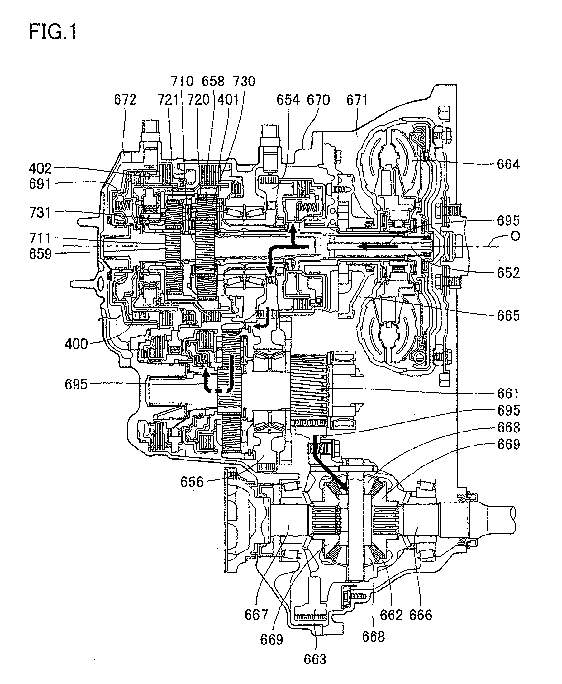
[0023]FIG. 1 is a schematic ...


PUM


Abstract

A power transmission device includes: a main case having an inside storing an oil; a drum carrying up the oil; and a partition wall partitioning the inside of the main case into a transmission gear housing containing the drum and a catch tank. An inner wall of the main case includes a down-extending portion extending down toward a feed opening of the catch tank, and extending toward the drum rather than along a vertical plane extending in the vertical direction as the down-extending portion extends downward, and a receding portion bordering on the down-extending portion and extending away from the drum from a bordering point where the receding portion borders on the down-extending portion.

Description

TECHNICAL FIELD[0001]The present invention relates to a power transmission device.BACKGROUND ART[0002]In order to reduce the oil agitation resistance and suppress generation of a useless power loss, various types of transmissions and the like mounted with a lubricating oil level adjustment device and a lubricating device for example have hitherto been proposed.[0003]For example, a power transmission device for a vehicle disclosed in Japanese Patent Laying-Open No. 2006-307908 is mounted with a lubricating device. This vehicle power transmission device is provided with a casing for storing a gear lubricating oil in its inner bottom portion, a first catch tank for catching to store the oil carried up by a ring gear, and a second catch tank provided separately from the first catch tank for catching to store the oil carried up by a drive gear.[0004]Further, a transfer case disclosed in Japanese Utility Model Laying-Open No. 6-14611 is mounted with a lubricating oil level adjustment devi...

Claims


Application Information

Patent Timeline
IPC IPC(8): F16H57/04
CPCF16H57/0409F16H57/0423F16H57/0447Y10T74/2186F16H57/0457F16H57/0484F16H57/045
Inventor IWATA, SHIGETSUGUKOHNO, TETSUYA
Owner TOYOTA JIDOSHA KK
Why Eureka
Try Eureka