
Photonic switch using time-slot interchange

a photonic switch and time-slot technology, applied in the direction of multiplex communication, time-division multiplexing selection, electrical apparatus, etc., can solve the problems of increasing the difficulty of building electronic switches, adding considerable expense to electronic switches, and electronic signals travelling only a limited distan

Inactive Publication Date: 2005-08-23
FUTUREWEI TECH INC
View PDF19 Cites 21 Cited by
  • Summary
  • Abstract
  • Description
  • Claims
  • Application Information

AI Technical Summary

Benefits of technology

The present invention is a telecommunications switch that combines the benefits of electronics and optics to overcome the bandwidth bottleneck of electronics switching. It uses optical switches that can switch quickly and can handle the routing of packets or cells. The switch uses a schedule that is not directly determined by the input stream, and the reordering unit can rearrange the order of data units within data streams to correspond to the switch schedule. The switch can handle short (nanosecond) packets and can be reconfigured quickly. The invention also matches the properties of an optical switch and allows for the switching of short packets while reconfiguring the switch only once every sub-frame. The switch can be controlled with a fixed or adaptive pattern, and the configuration of the switch does not directly depend upon the data it is switching.

Problems solved by technology

These trends make it increasingly difficult to build electronic switches.
These wide paths add considerable expense to an electronic switch.
Also, electronic signals can travel only a limited distance due to attenuation.
This further complicates the design of electronic switches, particularly as the number of ports increases.
While an all-optical switch addresses the problem of electronic bandwidth, it has difficulty performing the logic needed to route packets or providing the memory required for packet buffering.
Also, optical switches typically switch very slowly (tens of microseconds to hundreds of milliseconds), making it impossible to switch individual packets or cells that may be less than 10 nanoseconds long (e.g., a 40-byte packet at OC768 lasts only 8 ns).
The switch schedule may be fixed and balanced, or it may be unbalanced.

Method used


Image

  • Photonic switch using time-slot interchange
  • Photonic switch using time-slot interchange
  • Photonic switch using time-slot interchange

Examples


Embodiment Construction

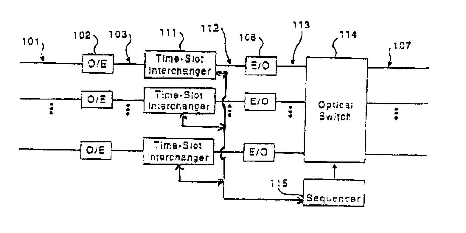
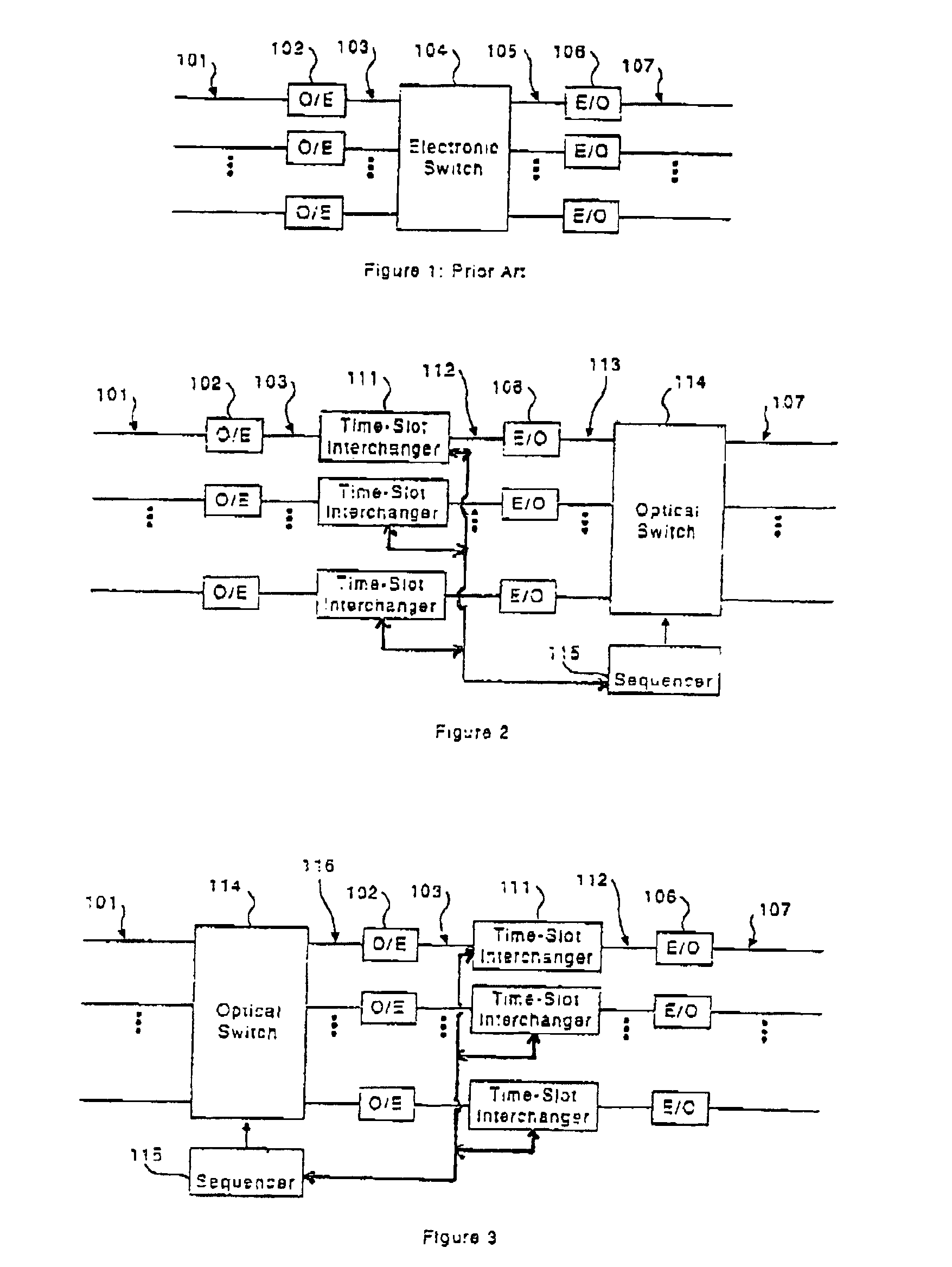
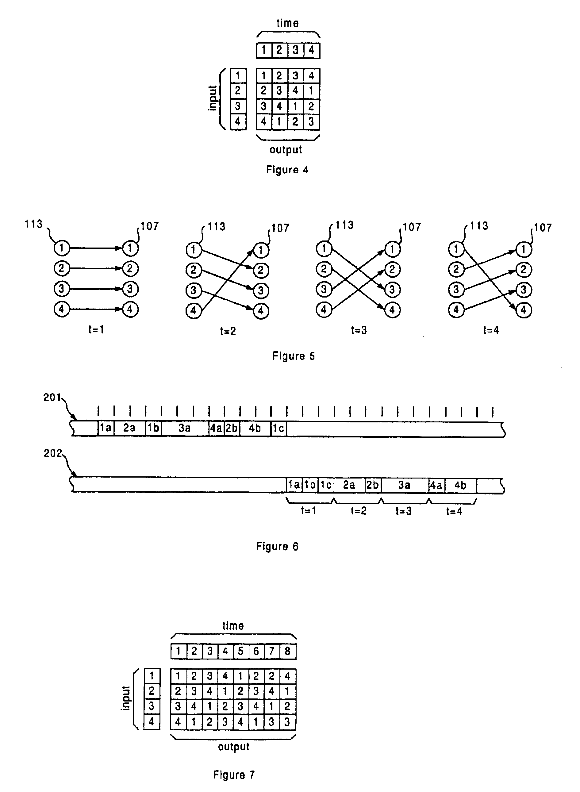
[0022]The present invention operates by converting the incoming streams to electronic form, but performs no switching on these electronic streams. As illustrated in FIG. 2, each electronic input stream 103 is input to a time-slot interchanger (TSI) 111. The TSI examines the packets within an input stream, using logic to make routing decisions, and reorders them in time (exchanging their time slots) so that packets traveling to a given output are grouped together in time. The reordered streams 112 are then converted back to optical form. These reordered optical stream 113 are then input to an all-optical switch that changes its connectivity in a fixed pattern at a relatively slow rate. Each TSI schedules the packets entering the optical switch to arrive at a time when its input is connected to the packet's destination.

[0023]FIG. 6 shows an input stream of packets 201 on an input line 101 and a reordered stream of packets 202 on internal line 113. Each packet is marked with a number d...


PUM


Abstract

An optical data stream is converted to electrical signals which are applied to a time-slot interchanger. The time-slot interchanger recorders the packets or cells of the data stream to correspond to the schedule of an optical switch. The time-slot interchanger may contain a plurality of FIFOs implemented as circular buffers in a single dual port memory. The switch schedule may be determined by the average load between inputs and outputs and may be determined by the number of packets or cells queued from each input or each output in the time-slot interchangers.

Description

BACKGROUND OF THE INVENTION[0001]High-speed telecommunications switches accept optical inputs and produce optical outputs but internally involve almost entirely electronic switching. Single-mode optical fibers are the technology of choice for long-haul transmission of information because they have very wide bandwidth, low attenuation, and low dispersion, making it possible to transmit information at very high bit rates (1010 b / s) over long distance (105 m) without the need of repeaters. Digital electronics, however, is the technology of choice for switching. Digital integrated circuits can switch connections in less than a nanosecond, and 105 to 106 digital gates can be incorporated on a single integrated circuit facilitating construction of the logic that controls a fast switch on a cycle by cycle basis.[0002]FIG. 1 shows a block diagram of prior art telecommunications switch. Inputs arrive on single-mode optical fibers 101. In a typical application, these fibers carry a serial bit...

Claims


Application Information

Patent Timeline
Patent Type & Authority Patents(United States)
IPC IPC(8): H04Q3/52H04Q11/00H04Q11/04
CPCH04Q11/0005H04Q11/0478
Inventor CARVEY, PHILIP P.DALLY, WILLIAM J.
Owner FUTUREWEI TECH INC
Learn More