Power and electrical signal interface for a therapeutic bed

a technology of power and electrical signal, applied in the field of therapeutic beds, can solve the problems of electrical intermittence and detrimental to the therapy of patients

Inactive Publication Date: 2005-08-30
HUNTLEIGH TECH LTD
View PDF13 Cites 37 Cited by
  • Summary
  • Abstract
  • Description
  • Claims
  • Application Information

AI Technical Summary

Benefits of technology

[0007]A therapeutic bed in accordance with the present invention is provided comprising a base frame, a patient support platform rotatably mounted on the base frame for rotational movement about a longitudinal rotational axis of the patient support platform, and a drive system for rotating the patient support platform on the base frame. A direct, wired connection is provided to the patient support platform that allows for a complete rotation of the patient support platform in either direction. The necessary electrical wires are housed within a chain-like cable carrier that is disposed within an annular channel attached to the patient support platform. An annular cover is installed adjacent the annular channel to retain the cable carrier within the annular channel, but the annular cover is not attached to the annular channel. Rather, the annular cover is attached to the nonrotating part of the bed. One end of the cable carrier is attached to the annular channel, and the other end is attached to the annular cover. The length of the cable carrier is sufficient to allow a full 360 degree rotation of the patient support platform in either direction from 0 degrees supine flat while maintaining a direct electrical connection.

Problems solved by technology

One of the problems in the art of prone positioning therapeutic beds is to provide electrical signal and power connections to the bed for both the power and controller equipment that moves the bed and for the patient monitoring systems on the bed.
However, due to vibration and other abrupt movements, such wire brushes cause problems of electrical intermittence, which can be detrimental to the therapy of the patient.

Method used


Image

  • Power and electrical signal interface for a therapeutic bed
  • Power and electrical signal interface for a therapeutic bed
  • Power and electrical signal interface for a therapeutic bed

Examples


Embodiment Construction

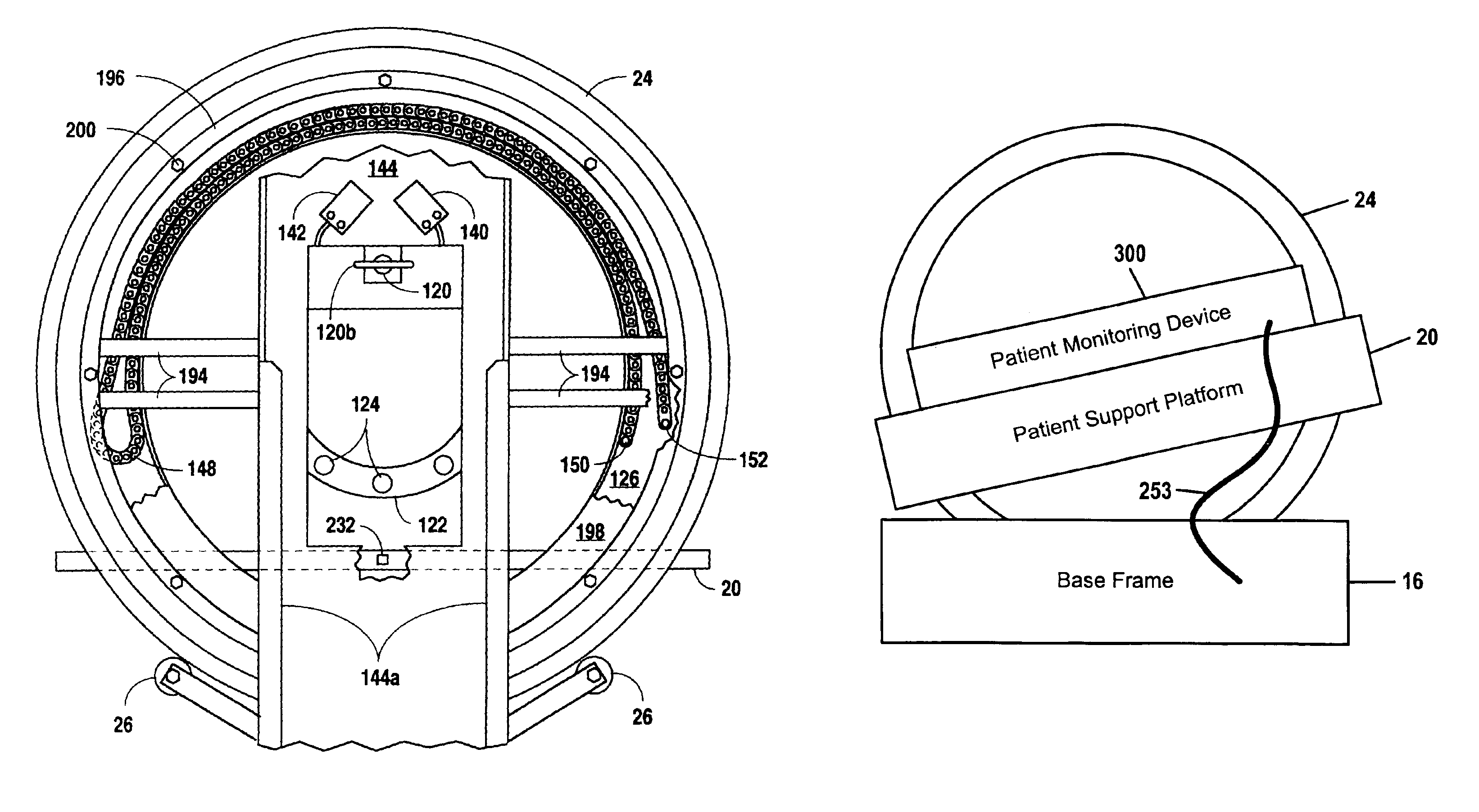
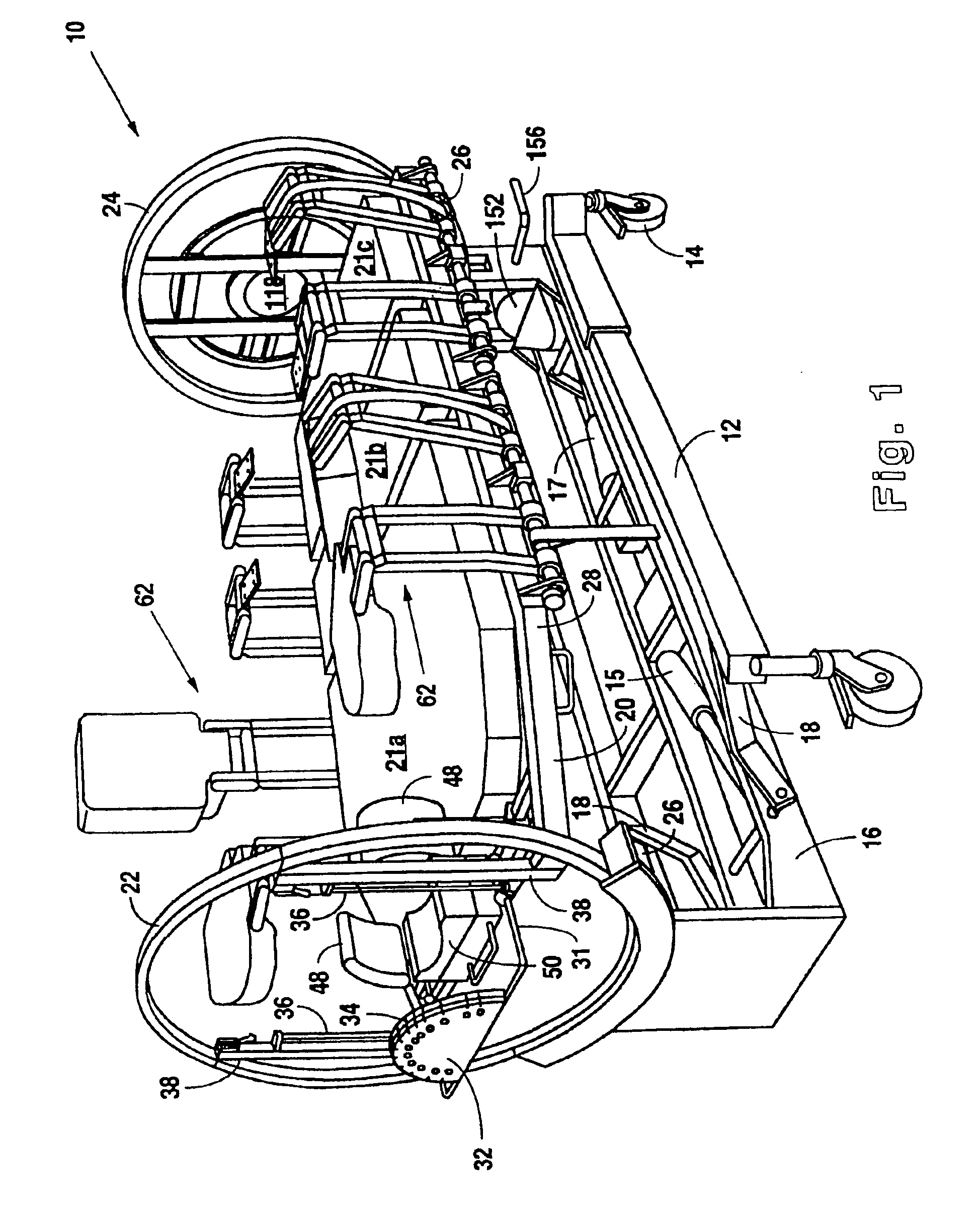
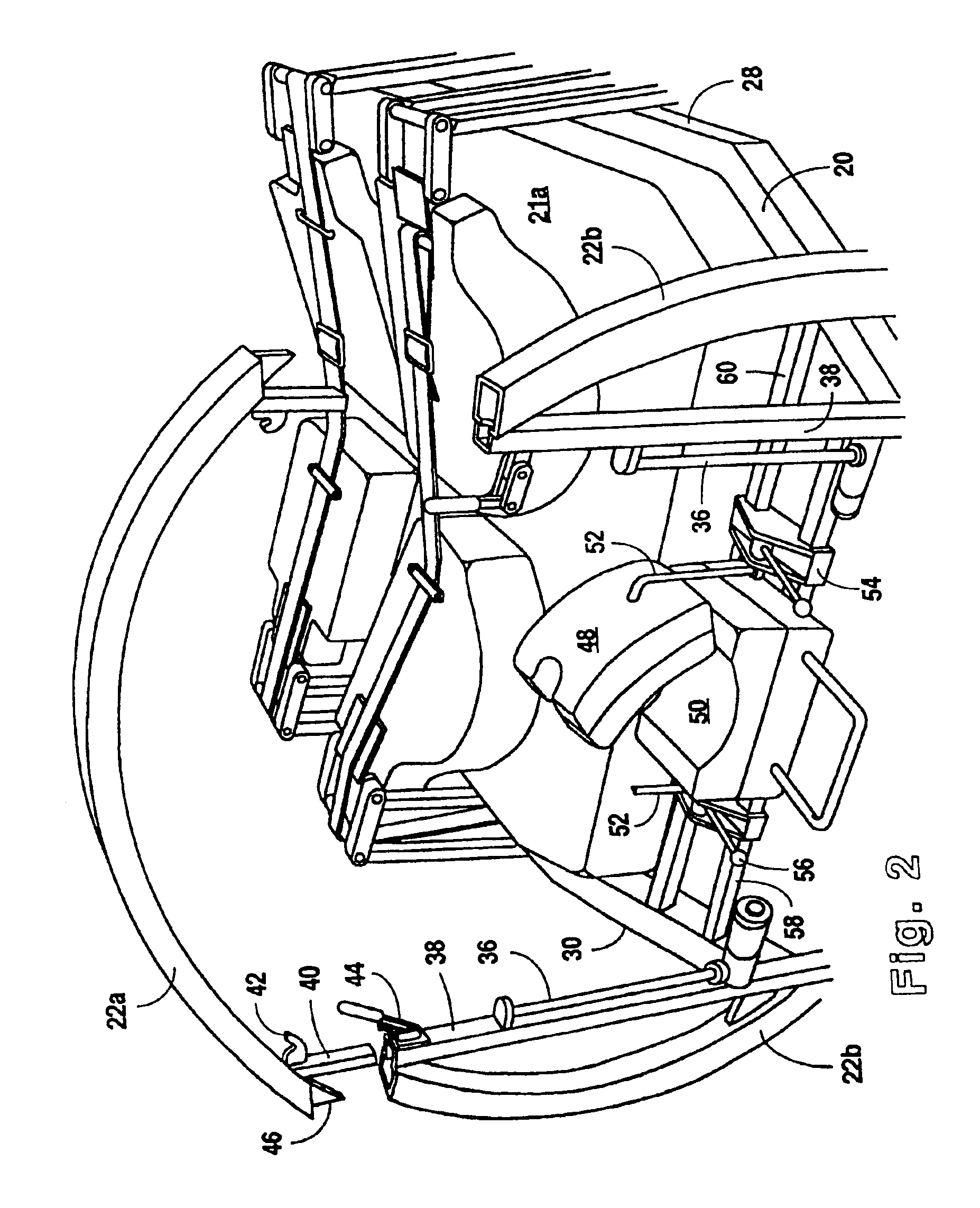
[0037]Referring to FIGS. 1 and 2, a therapeutic bed 10 in accordance with the present invention preferably comprises a ground engaging chassis 12 mounted on wheels 14. A base frame 16 is mounted on chassis 12 with pivot linkages 18. Rams 15, 17 housed within base frame 16 cooperate with pivot linkages 18 to form a lift system to raise and lower base frame 16 on chassis 12. A patient support platform 20 having upright end rings 22, 24 is rotatably mounted on base frame 16 with rollers 26 such that patient support platform 20 may rotate about a longitudinal axis between a supine position and a prone position. Side support bars 28, 30 extend between end rings 22, 24. At the head of bed 10, a guide body 32 having a plurality of slots 34 for routing patient care lines (not shown) is slidably mounted on rails 36 with support rod 31. Similarly, at the foot of bed 10, a central opening 118 is provided for receiving a removable patient care line holder (not shown) having a plurality of circu...


PUM


Abstract

A direct electrical signal and power interface is provided to the patient support platform of a therapeutic bed that allows for a complete rotation of the patient support platform in either direction. In one embodiment, an electrical signal and / or power cable is housed within a chain-like cable carrier that is disposed within an annular channel attached to the patient support platform. In another embodiment, a flexible ribbon cable is disposed within the annular channel. The cable carrier or ribbon cable is long enough to allow a full 360 degrees of rotation of the patient support platform in either direction from 0 degrees supine flat while maintaining a direct electrical signal or power connection. To ensure that the electrical signal and power connection is not articulated beyond its physical limit as a result of manually rotating the bed in the emergency backup mode, a mechanical stop is provided to limit rotation of the patient support platform to about 730 degrees. Sensors are provided to detect activation of the mechanical stop.

Description

RELATED APPLICATION INFORMATION[0001]This application is a continuation of PCT / IE02 / 00085 file Jun. 26, 2002, which is a division of Ser. No. 09 / 812,552 filed Mar. 29, 2001 now U.S. Pat. No. 6,671,905.BACKGROUND OF THE INVENTION[0002]1. Field of the Invention[0003]This invention relates generally to therapeutic beds, and more particularly to beds with a patient support platform operable to rotate about a longitudinal axis of the platform.[0004]2. Description of the Related Art[0005]One of the problems in the art of prone positioning therapeutic beds is to provide electrical signal and power connections to the bed for both the power and controller equipment that moves the bed and for the patient monitoring systems on the bed. To allow unrestricted rotation of the bed of WO 99 / 62454, for example, electrical power has been provided by wire brushes at the interface between the rotating part of the bed and the nonrotating part of the bed. However, due to vibration and other abrupt moveme...

Claims


Application Information

Patent Timeline
Patent Type & Authority Patents(United States)
IPC IPC(8): A61G7/00A61G7/05
CPCA61G7/001A61G7/008A61G7/018A61G7/0507A61G2007/051A61G2007/0513A61G2007/0519A61G2007/0522A61G2007/0524A61G2007/0527A61G2203/34A61G2210/50A61G2203/42A61G7/051A61G7/0513A61G7/0519A61G7/0522A61G7/0524A61G7/0527
Inventor KRYWICZANIN, WLADYSLAW H.NIEDERKROM, CHRISTOPHER T.BEARD, MARKWHYTE, DAVID
Owner HUNTLEIGH TECH LTD
Why Eureka
Try Eureka