Tie

a tie and tie technology, applied in the field of tie, can solve the problems of overtightening the tie, excessive compression, and the difficulty of assessing the traction force on the strap, and achieve the effect of accurate assessment of the traction force exerted

Inactive Publication Date: 2005-08-30
LEGRAND SNC
View PDF10 Cites 14 Cited by
  • Summary
  • Abstract
  • Description
  • Claims
  • Application Information

AI Technical Summary

Benefits of technology

[0017]Thus the frangible bridges with different sections together form a strain gauge enabling the user to secure the components to be gripped by the tie in a sufficiently rigid and stable manner whilst avoiding excessive compression likely to damage them.
[0030]The successive frangible bridges can instead have sections increasing from one of the segments toward the other, so that it is possible to obtain a relatively accurate assessment of the traction force exerted on the strap when tightening the tie, according to the number of bridges that break.

Problems solved by technology

However, they have the major drawback of being fragile, and excessive compression when tightening the tie tends to damage them.
This is because the user has no way to assess the traction force that must be applied to the tie to hold the cables together without damaging them with the result that he usually overtightens the tie, assuming that its extensibility will suffice to absorb the excess force.
The traction force exerted on the strap is even more difficult to assess since the tie is usually fitted by means of a tool specifically designed for this purpose.

Method used


Image

  • Tie
  • Tie
  • Tie

Examples


Embodiment Construction

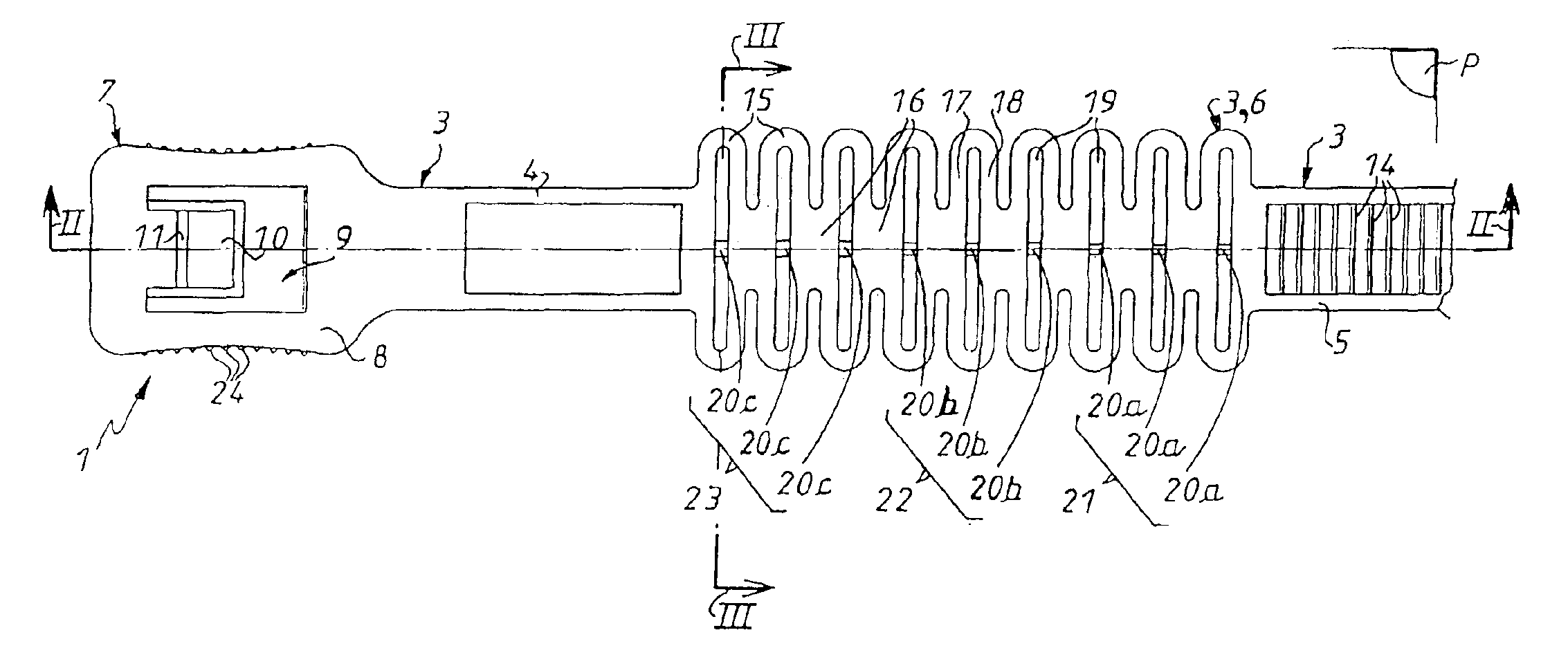
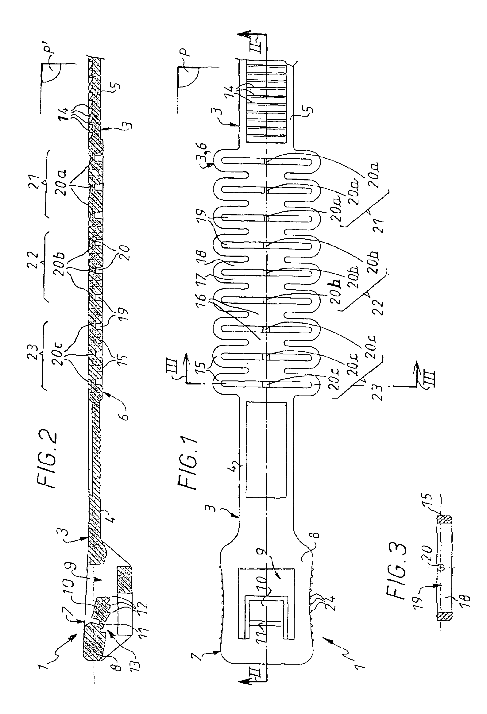
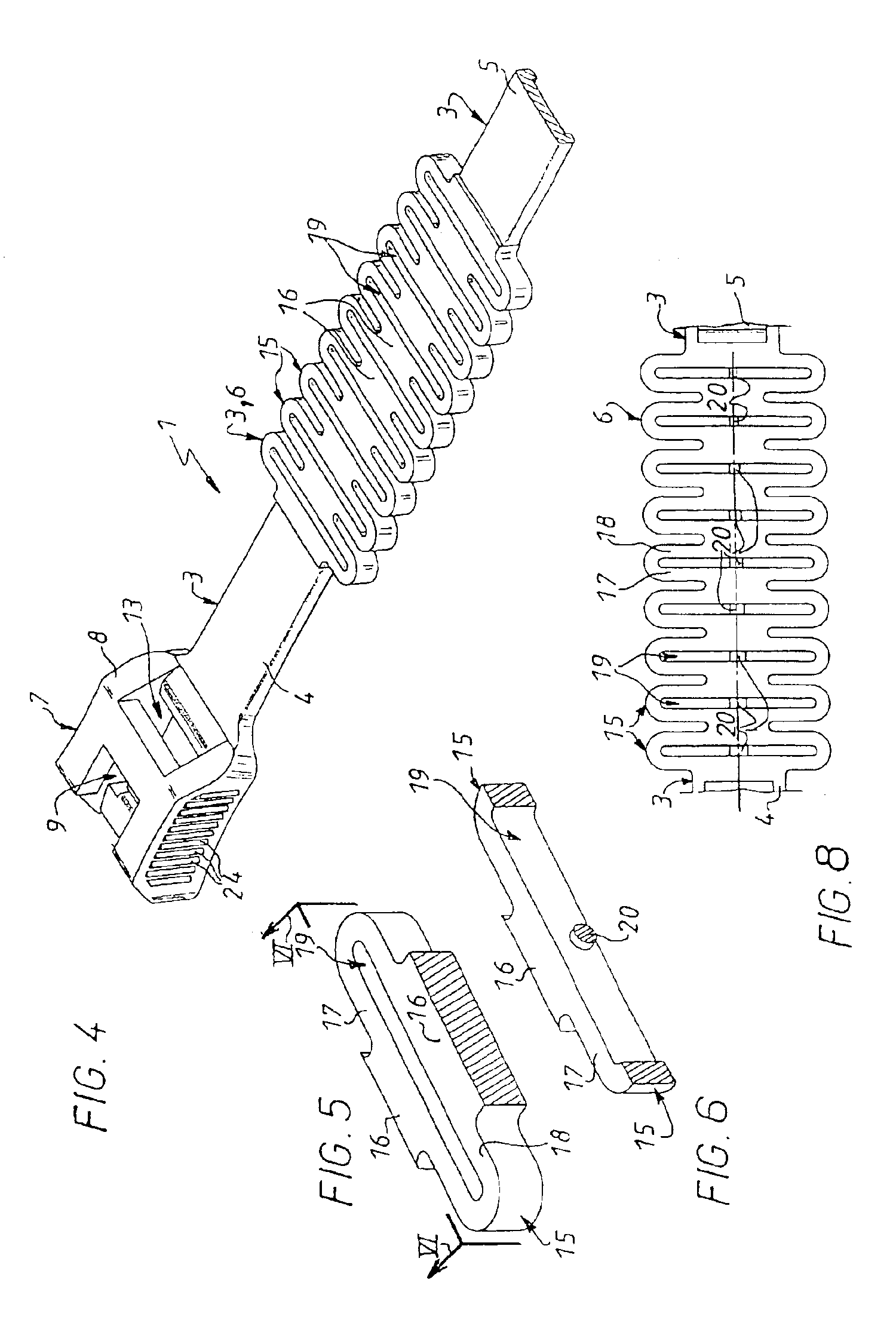
[0040]FIG. 1 shows a tie 1 adapted to grip a plurality of elongate components 2 to hold them together.

[0041]In this instance the components 2 are electrical or optical cables, in particular VDI cables, which are particularly fragile.

[0042]All portions of the one-piece tie 1, as described hereinafter, are made in one piece, in fact molded in one piece, since in this embodiment the tie 1 is formed by molding a synthetic material, preferably polyamide.

[0043]The tie 1 includes a strap 3 which, when relaxed (i.e. in the absence of any load), is rectilinear and thus defines a longitudinal direction.

[0044]The strap 3 has a first end segment 4 and a second end segment 5 connected by an extensible intermediate portion 6.

[0045]The tie 1 further includes, at the end of the strap 3, and on the other side of the first segment 4 from the intermediate portion 6, a closure head or buckle 7 whose function will become apparent hereinafter.

[0046]Accordingly, the tie 1 includes, in succession: the buck...


PUM


Abstract

A tie includes a strap having two end segments connected by an extensible intermediate portion provided with a succession of frangible bridges each connecting a first part of the intermediate portion to a second part of the intermediate portion. Two or more of the frangible bridges have different sections.

Description

BACKGROUND OF THE INVENTION[0001]1. Field of the Invention[0002]The invention relates to ties.[0003]It concerns a tie including a strap having two end segments connected by an extensible intermediate portion provided with a succession of frangible bridges each connecting a first part of said portion to a second part of said portion.[0004]2. Description of the Prior Art[0005]U.S. Pat. No. 3,875,620 shows the application of a tie of the above kind to attaching the branches of a tree or a shrub to a support.[0006]The tie expands progressively as the branch grows by successive rupturing of the frangible bridges.[0007]Ties of the above kind have many other applications, in particular for holding together electrical or optical cables, for example voice / data / image (VDI) cables.[0008]Given their many applications in data transmission, VDI cables are increasingly widely used.[0009]However, they have the major drawback of being fragile, and excessive compression when tightening the tie tends ...

Claims


Application Information

Patent Timeline
Patent Type & Authority Patents(United States)
IPC IPC(8): F16L3/22F16L3/233
CPCF16L3/2334Y10T24/141Y10T24/1408Y10T24/153Y10T24/1498
Inventor BARRIUSO, JEAN-PIERRECORNU, HERVE
Owner LEGRAND SNC
Why Eureka
Try Eureka