
Cold water inlet for reducing accumulation of scale

a technology of scale accumulation and cold water, which is applied in the direction of fluid heaters, machines/engines, lighting and heating apparatus, etc., can solve the problems of reducing the efficiency of water heaters, and achieve the effects of reducing scale accumulation, and reducing the amount of water flow

Active Publication Date: 2005-08-30
BRADFORD WHITE
View PDF75 Cites 6 Cited by
  • Summary
  • Abstract
  • Description
  • Claims
  • Application Information

AI Technical Summary

Benefits of technology

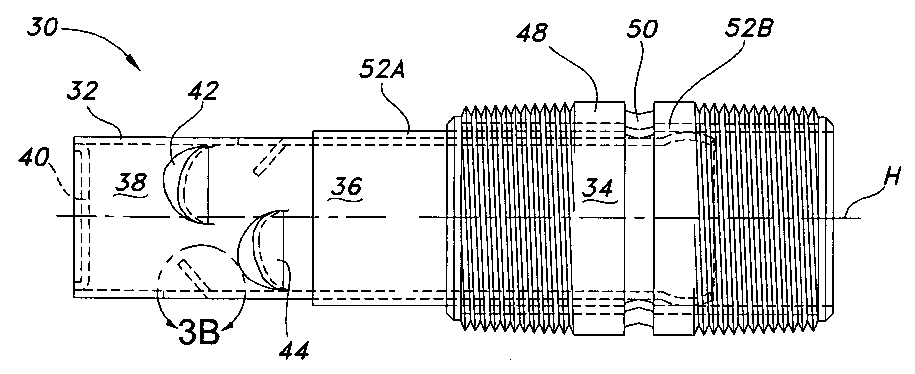
[0006]In one exemplary embodiment, this invention provides a cold water inlet for delivering water into a water tank of a water heater. The water tank has a side wall, a tank bottom, and at least one flue extending upwardly through the water tank. The cold water inlet includes an inlet conduit configured to extend along a horizontal axis through the side wall of the water tank, into a bottom portion of the water tank, and toward the flue. The inlet conduit includes a proximal conduit portion defining a flow opening for water flow into the inlet conduit, an intermediate conduit portion extending from the proximal conduit portion and defining a flow passage for the water flow, and a distal conduit portion extending from the intermediate portion and terminating at a closed end configured to reduce the amount of the water flow directed toward the flue. The cold water inlet further includes flow openings defined in the distal conduit portion to permit the water flow to exit the inlet conduit. The flow openings are spaced about a circumference of the inlet conduit, thereby eliminating the need to align the inlet conduit with respect to the tank bottom. Deflectors are positioned along the distal conduit portion of the inlet conduit proximal respective ones of the flow openings. The deflectors are oriented to extend distally from the inlet conduit and toward the horizontal axis for deflecting the water flow. The closed end and the deflectors of the inlet conduit coact, as the water flows into the water tank, to direct the water flow away from the flue and toward the side wall and tank bottom of the water tank, thereby reducing an accumulation of scale on the side wall and tank bottom.
[0008]In yet another exemplary embodiment, a method is provided for delivering cold water into a water heater tank having a side wall, a tank bottom, a cold water inlet, and at least one flue extending upwardly through an interior of the water tank. The method delivers cold water into the water heater tank while reducing the amount of water flow directed toward the flue, eliminating the need to align the cold water inlet with respect to the tank bottom, and directing water flow toward the side wall and the tank bottom to reduce an accumulation of scale on the side wall and the tank bottom. Water is delivered through an inlet conduit along a horizontal axis through the side wall of the water tank, into a bottom portion of the water tank, and toward the flue. Water flow is substantially prevented from the inlet conduit along the horizontal axis toward the flue, thereby reducing the amount of water flow directed toward the flue. Water flow is delivered from the inlet conduit through flow openings defined in the inlet conduit and spaced about a circumference of the inlet conduit, thereby eliminating the need to align the inlet conduit with respect to the tank bottom. Water flow is deflected proximal the flow openings away from the flue and toward the side wall and the tank bottom of the water heater tank, thereby reducing an accumulation of scale on the side wall and the tank bottom.

Problems solved by technology

Accumulated sediment tends to harden, forming a scale on various tank surfaces, which reduces water heater efficiency and, in some cases, can lead to failure.

Method used


Image

  • Cold water inlet for reducing accumulation of scale
  • Cold water inlet for reducing accumulation of scale
  • Cold water inlet for reducing accumulation of scale

Examples


Embodiment Construction

[0020]Although the invention is illustrated and described herein with reference to specific embodiments, the invention is not intended to be limited to the details shown. Rather, various modifications may be made in the details within the scope and range of equivalents of the claims and without departing from the invention.

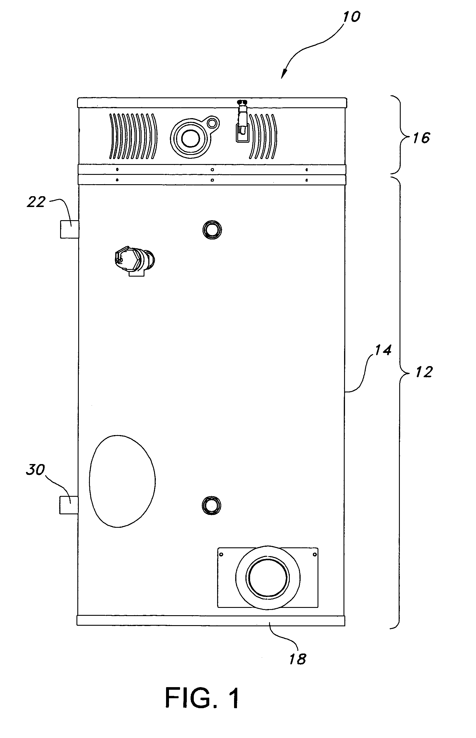
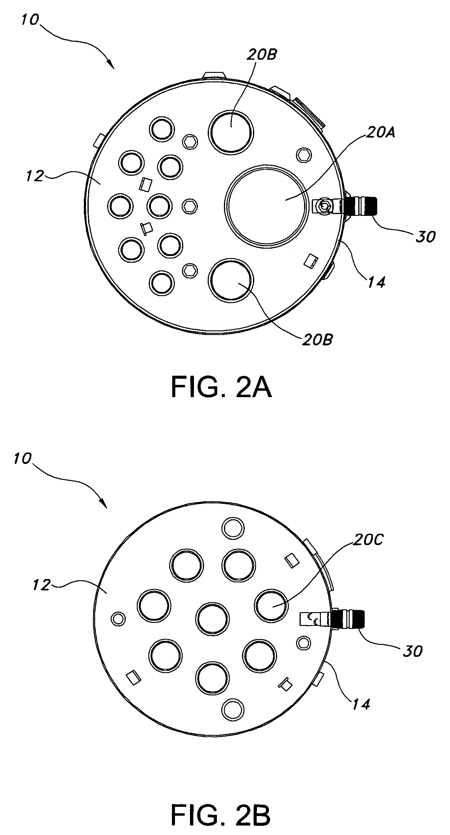
[0021]Referring to the figures generally, an exemplary embodiment of a cold water inlet 30 for delivering water into a water tank 12 of a water heater 10 is provided. The water tank 12 has a side wall 14, a tank bottom 18, and at least one flue 20 extending upwardly through the water tank 12. The cold water inlet 30 includes an inlet conduit 32 configured to extend along a horizontal axis H through the side wall 14 of the water tank 12, into a bottom portion of the water tank 12, and toward the flue 20. The inlet conduit 32 includes a proximal conduit portion 34 defining a flow opening for water flow into the inlet conduit 32, an intermediate conduit portion 36 ex...


PUM


Abstract

A cold water inlet for a tank of a water heater is provided. The inlet includes an inlet conduit configured to extend toward a flue extending upwardly through the tank. The inlet conduit includes a proximal, intermediate, and distal conduit portion, the distal portion terminating at a closed end configured to reduce the amount of the water flow directed toward the flue. The cold water inlet further includes flow openings defined in the distal portion to permit the water flow to exit the inlet conduit. Deflectors are positioned along the distal portion proximal respective ones of the flow openings, and are oriented for deflecting the water flow. The closed end and the deflectors of the inlet conduit coact, as the water flows into the tank, to direct the water flow away from the flue and toward the side wall and bottom of the tank, thereby reducing an accumulation of scale.

Description

FIELD OF THE INVENTION[0001]This invention relates to an inlet for a water heater, and more particularly, to a cold water inlet adapted to reduce the accumulation of scale within the water heater.BACKGROUND OF THE INVENTION[0002]Heating of water promotes the precipitation of sediment. Accumulated sediment tends to harden, forming a scale on various tank surfaces, which reduces water heater efficiency and, in some cases, can lead to failure.[0003]Various inlets have been proposed over the years in an attempt to overcome one or more of these problems. U.S. Pat. No. 4,257,355 to Cook describes a cold water inlet tube with several nozzles to provide jet-like discharges of incoming cold water downwardly at an angle in the general direction of the tank's bottom. A nozzle is also provided at the top of the inlet tube to discharge a jet of cold water upwardly toward the hot water stored in the upper portion of the tank. The angular nozzles in the bottom of the tube are intended to agitate a...

Claims


Application Information

Patent Timeline
Patent Type & Authority Patents(United States)
IPC IPC(8): F24H9/00F24H9/12
CPCF24H9/0042F24H9/124F24H9/133
Inventor SCOTT, TIMOTHY D.GORDON, MICHAELSTAFFORD, CHRISTOPHER P.RODRIGUEZ, DARRELL
Owner BRADFORD WHITE
Learn More