Seat position detection unit

a detection unit and seat technology, applied in the field of seat for a vehicle, can solve the problems of further complicated achieve the effects of improving workability of assembling the seat position detection unit, reducing the number of parts, and improving the number of parts

Inactive Publication Date: 2005-08-30
HONDA MOTOR CO LTD
View PDF9 Cites 32 Cited by
  • Summary
  • Abstract
  • Description
  • Claims
  • Application Information

AI Technical Summary

Benefits of technology

[0017]Thereby, when assembling the seat position detection unit, the positioning step, in which the accurate positioning of the position sensor or the detecting object is performed, can be omitted. Thus, the workability of the assembling of the seat position detection unit will be improved. Additionally, the seat position detecting object can measure whether the seat is positioned at the prescribed position.
[0018]In the present invention, still furthermore, the mounting member and one of the position sensor and the detecting object are formed into a single piece, and this lessens the numbers of the parts that constitutes the seat position detection unit. Thus, the workability of the assembling of the seat position detection unit will further be improved.

Problems solved by technology

Thus, the workability of the assembling has been made complicated.
Thus, in this seat position detection unit, the accurate positioning of the bracket and the support member had to be performed with fastidious care.
Thereby, the workability of the assembling of the seat position detection unit has further been complicated.

Method used


Image

  • Seat position detection unit
  • Seat position detection unit
  • Seat position detection unit

Examples


Embodiment Construction

[0025]The preferred embodiment of the present invention will be explained with reference to the attached drawings.

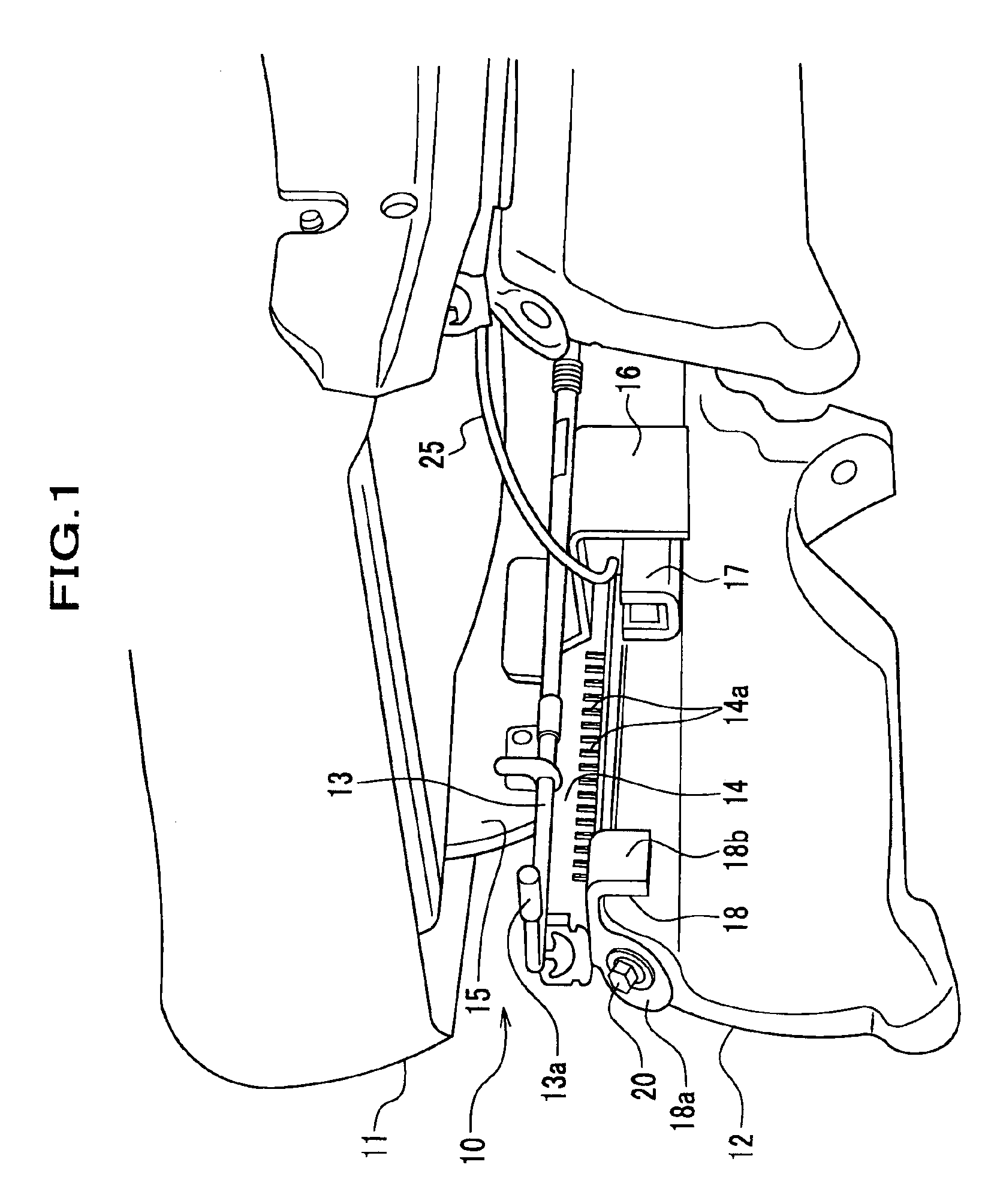
[0026]As shown in FIG. 1, a seat position detection unit 10, which is mounted on a floor (not shown) of a vehicle through a base member 12, is disposed at the bottom of a seat 11.

[0027]Here, intervening members between the floor and the seat position detection unit, such as the base member 12, shall be contained in a term of “floor”.

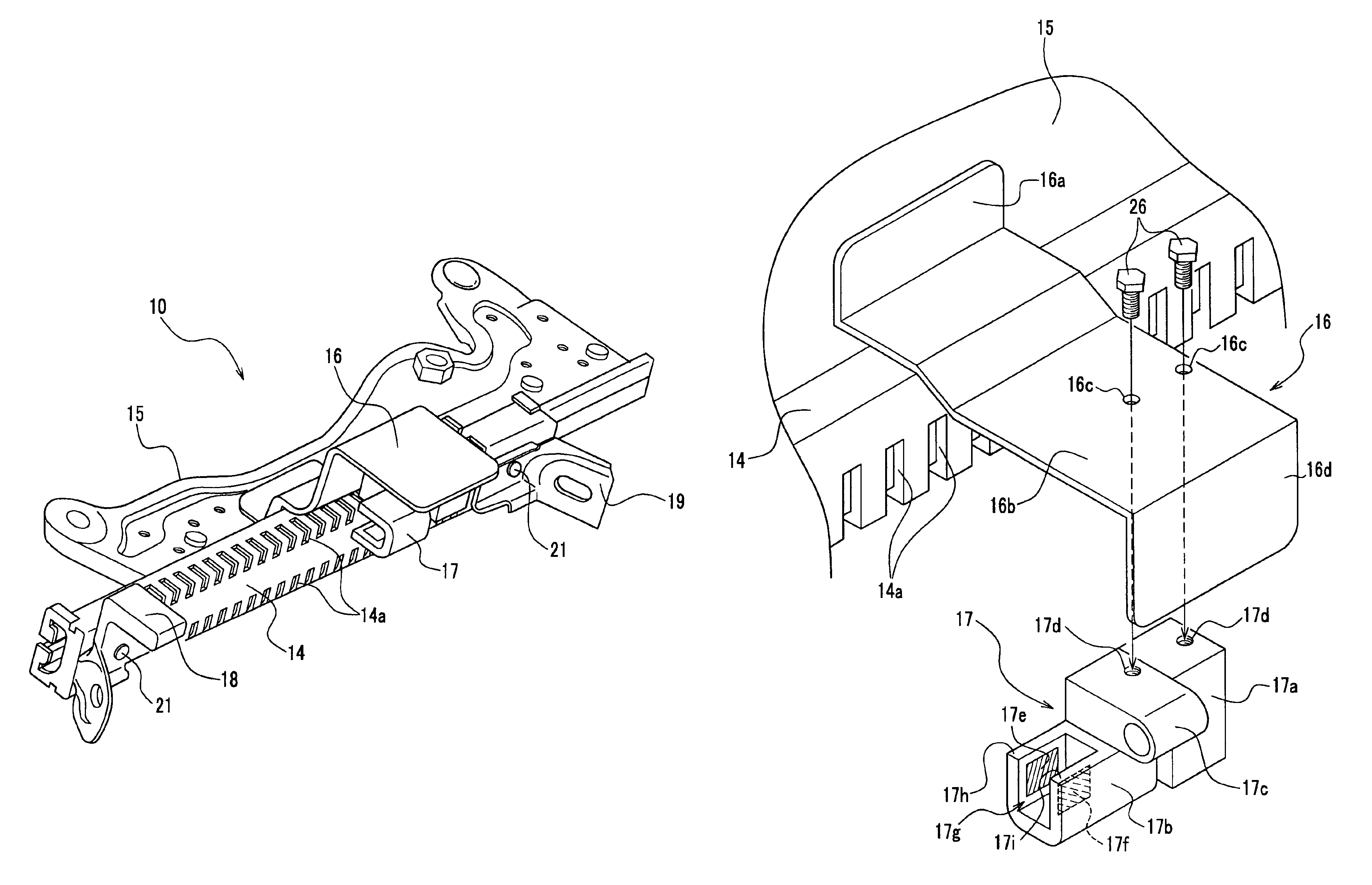
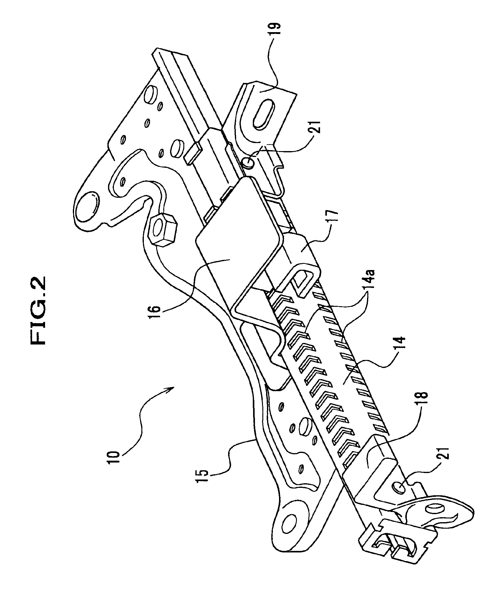
[0028]A movable member 15, described in further detail below, is one of components of the seat position detection unit 10, and is connected to the seat 11 at top part thereof. The bottom part of the movable member 15 is put together with the stationary member 14 so that the movable member 15 is allowed to slide along the stationary member 14. Thereby, the seat 11 which is connected to the movable member 15 is allowed to slide along the stationary member 14.

[0029]A seat position adjustment device 13, which adjusts the position in the fore-and-...


PUM


Abstract

A seat position detection unit which has a movable member, a stationary member, an attaching member, a position sensor, and a detecting object.In this seat position detection unit, the movable member is attached to a bottom of a seat and is put together with the stationary member so that the movable member is allowed to slide along the stationary member. The position sensor and the detecting object to be detected by the position sensor are provided to the stationary member and the movable member, separately. Here, the stationary member is attached to a floor through the attaching member.One of the position sensor and the detecting object that is attached to the stationary member and the mounting member are provided as a single piece.

Description

BACKGROUND OF THE INVENTION[0001]1. Field of the Invention[0002]The present invention relates to a seat for a vehicle, preferably to a vehicle seat which slides with respect to a floor of the vehicle, and which is equipped with a seat position detector. More specifically, the present invention relates to a seat position detection unit, which measures the position of the seat.[0003]2. Description of Relevant Art[0004]As an example of a seat position detection unit, the seat position detection unit disclosed in U.S. Pat. No. 6,053,529 can be cited.[0005]The seat position detection unit disclosed in U.S. Pat. No. 6,053,529 has a stationary rail, which is fixed to a floor of a vehicle, and a movable rail, which is attached to a seat of the vehicle and is put together with the stationary rail so that the movable rail (seat) is allowed to slide along the stationary rail.[0006]In this seat position detection unit, a magnetometric sensor is provided on the stationary rail, and a detecting o...

Claims


Application Information

Patent Timeline
Patent Type & Authority Patents(United States)
IPC IPC(8): B60N2/00B60R21/01B60N2/06G01B21/00B60R21/015
CPCB60R21/01554B60N2/002
Inventor NISHIDE, HARUTOMIISONAGA, KAZUTOMO
Owner HONDA MOTOR CO LTD
Why Eureka
Try Eureka