In-vivo extendable element device and system, and method of use

a technology of extendable elements and devices, applied in the field of in vivo diagnosis and therapeutics, can solve the problems of complicated control, limited imaging capabilities of such endoscopic systems, and partial forward field of vision

Active Publication Date: 2005-08-30
GIVEN IMAGING LTD
View PDF26 Cites 311 Cited by
  • Summary
  • Abstract
  • Description
  • Claims
  • Application Information

AI Technical Summary

Benefits of technology

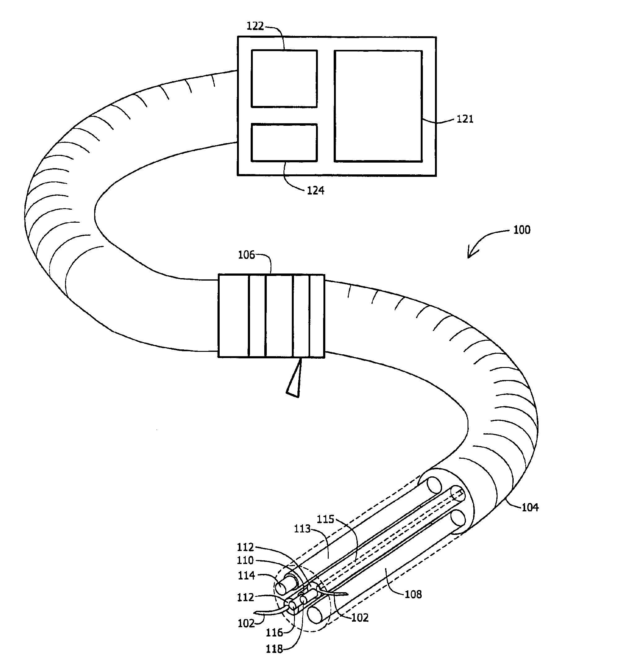
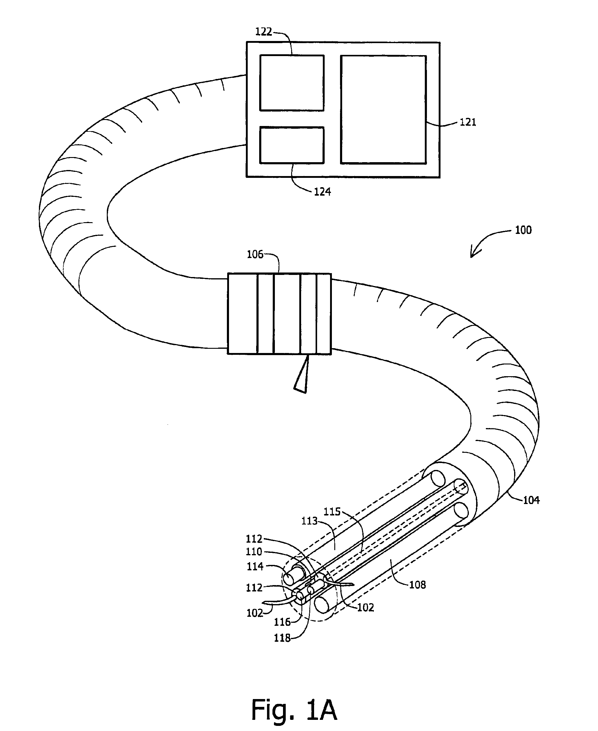
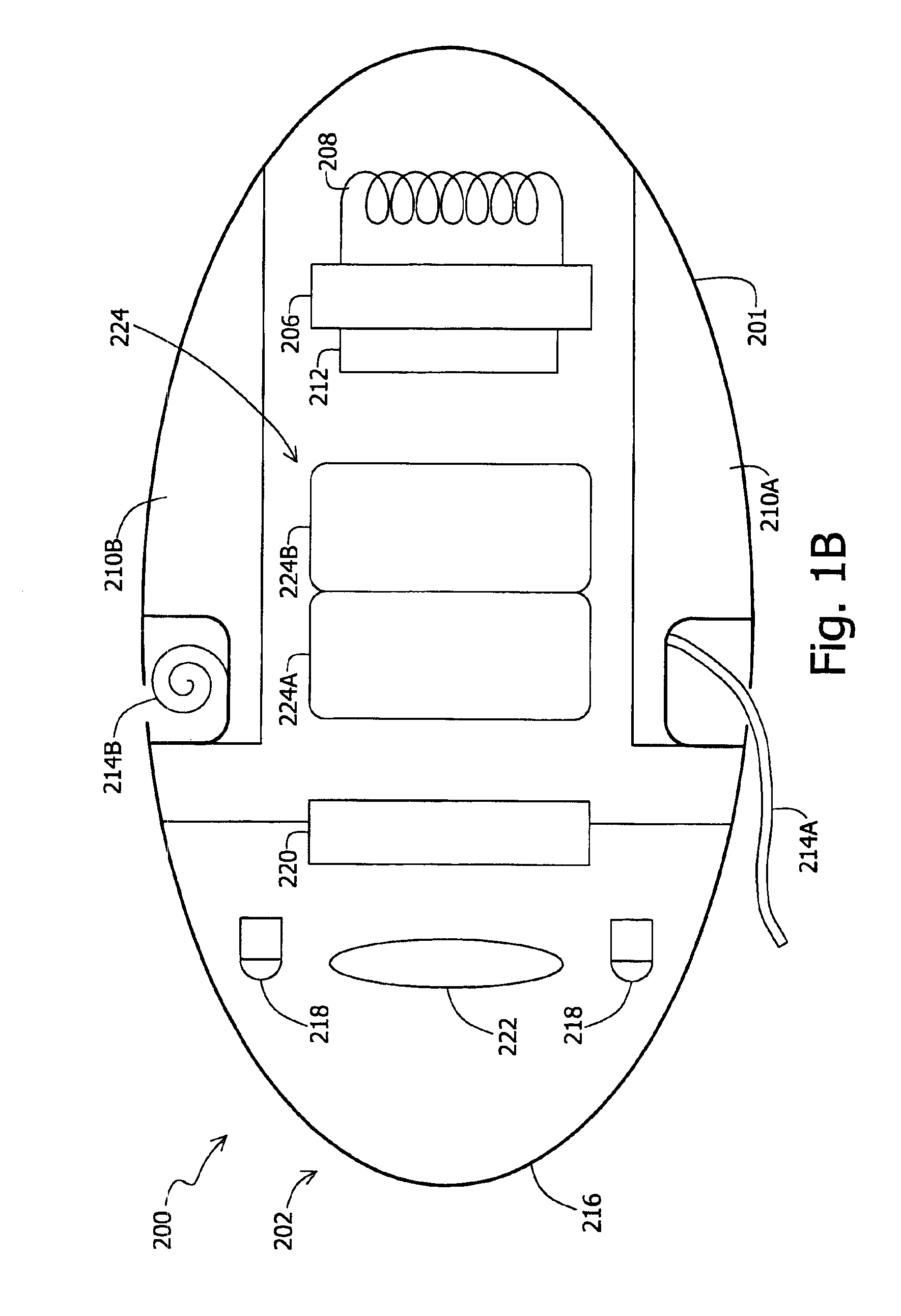
[0007]There is thus provided, according to an embodiment of the present invention, a typically in vivo system and / or device including one or more extendable and / or moveable elements or arms, which may be termed proboscises. The proboscises may, for example, act as one or more “arms” to perform a variety of tasks or, for example, may be used to propel, move, stabilize or hold the device. In some embodiments, the arms or proboscises may be progressively extendable, and the extension of the proboscis may be omni-directionally controlled by, for example, outside direction by an operator, or autonomously. In another embodiment of the present invention, an autonomous in vivo device may include one or more proboscises. In alternate embodiments, the extendable element may be used in a non-medical field or application. The device may be autonomous, and may include an on-board power supply, such as a battery or a power receiving system.
[0008]Various suitable structures for an arm or extendible element may be used. For example, in one embodiment, a plurality of segments may be used. A set of control wires may connect to the arm or element, and if segments are used may connect to individual segments. Devices that may be used to move the arm or element may include, for example, piezo material, shape memory material, motors, or other suitable elements.

Problems solved by technology

The imaging capabilities of such endoscopic systems may be limited and provide only a partial forward field of vision, although some endoscope systems do allow for the field of view to be changed.
Additionally, although a variety of medical instruments may be passed through the endoscopic tube to enable treatment at a site of interest, such instruments are usually relatively cumbersome and may require complicated controls and cause pain or discomfort to a patient.
The design of autonomous in-vivo devices, such as swallowable capsules, may be subjected to size constraints and other limitations.

Method used


Image

  • In-vivo extendable element device and system, and method of use
  • In-vivo extendable element device and system, and method of use
  • In-vivo extendable element device and system, and method of use

Examples


Embodiment Construction

[0021]In the following detailed description, numerous specific details are set forth in order to provide a thorough understanding of the invention. However it will be understood by those of ordinary skill in the art that the present invention may be practiced without these specific details. In other instances, well-known methods and procedures have not been described in detail so as not to obscure the present invention.

[0022]Throughout the specification the term “in-vivo procedures” may relate to any diagnostic and / or therapeutic procedures performed inside the human body, for example, but not limited to, procedures of gastroenterology, procedures within or on blood vessels, procedures of gynecology and laparoscopic surgery procedures.

[0023]Embodiments of the present invention relate to an in-vivo system and device-including one or more extendable elements or arms, which may be termed proboscises. In alternate embodiments, the extendable element may be used in a non-medical field or...


PUM


Abstract

An in-vivo device, such as an autonomous imager or other suitable in-vivo device, includes a moveable arm, extendible element, or proboscis. The in-vivo device may include sensors, such as imagers, etc. The device may transmit sensing information via, for example, wireless transmission, or wired transmission.

Description

RELATED APPLICATION DATA[0001]The present application claims benefit from prior U.S. Provisional Patent Application Ser. No. 60 / 421,788 filed on 29 Oct. 2002 and entitled “IN-VIVO EXTENDABLE ELEMENT DEVICE AND SYSTEM, AND METHOD OF USE”, incorporated by reference herein in its entirety.FIELD OF THE INVENTION[0002]The present invention relates to the field of in vivo diagnosis and therapeutics, more specifically, the present invention relates to a system and a device for in vivo diagnosis and therapeutics including an extendable and / or moveable element.BACKGROUND[0003]Devices and methods for performing in-vivo medical procedures and imagery are known in the art. Such devices may be, for example, inserted into a patient's body and advanced through internal lumens or cavities of the body to a site of interest located inside a patient's body.[0004]One group of in-vivo medical devices includes various endoscopic systems. The imaging capabilities of such endoscopic systems may be limited ...

Claims


Application Information

Patent Timeline
Patent Type & Authority Patents(United States)
IPC IPC(8): A61B5/07A61B5/00A61B1/00A61B
CPCA61B1/00156A61B1/041A61B5/0031A61B5/07A61B1/00085A61B1/00148
Inventor IDDAN, GAVRIEL J.
Owner GIVEN IMAGING LTD
Why Eureka
Try Eureka