
Method and apparatus for recovering load/unload zone real estate on data storage media in data storage devices to increase a data storage capacity thereof

a data storage device and load/unload zone technology, applied in the field of disk storage space improvement, can solve the problems of reducing the overall storage capacity of the drive by 5 to 15%, potentially risking media damage from slider-disk contact, etc., to increase the efficiency and storage capacity of the hard disk drive, reduce the problem of disk damage during l/ul, and reduce the effect of disk damage from l/ul

Inactive Publication Date: 2005-08-30
WESTERN DIGITAL TECH INC
View PDF17 Cites 20 Cited by
  • Summary
  • Abstract
  • Description
  • Claims
  • Application Information

AI Technical Summary

Benefits of technology

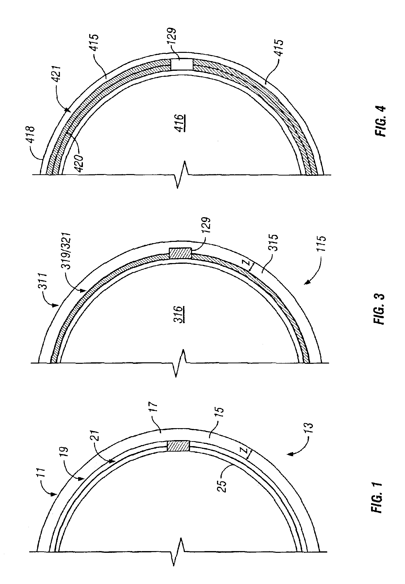
[0010]One embodiment of a hard disk drive apparatus and method constructed in accordance with the present invention utilizes hard disks that recover the historically unused read / write space or real estate located in the load / unload zone. Approximately one-half of the load / unload zone is recovered and available for reading and writing operations by forming a first (radially outermost) read / write track beginning immediately adjacent to the inner radial edge of the load / unload zone and proceeding radially inward from there to the “conventional” location of first tracks in the prior art. In an alternate embodiment of the present invention, almost the entire load / unload zone is recovered and available for reading and writing operations by aligning the first track with the center of the load / unload (L / UL) zone and proceeding radially inward from there as described above. Both of these embodiments make significant additional surface area on the disk available where, in the prior art, no data was stored, thereby increasing the efficiency and storage capacity of the hard disk drive.
[0011]The problem of disk damage during L / UL is reduced by designing the air bearing, suspension, ramp, and disk drive parameters (e.g., disk and L / UL speeds) such that head-disk contact is eliminated or reduced. Alternatively, the slider itself can be processed in such a way that any contact that does occur causes no damage or an acceptably small amount of damage to the disk. Rounding, which also is referred to as “blending,” slider corners and / or edges so that no sharp points (regions of high stress concentration) are presented to the disk surface during contact, is a demonstrated way to reduce disk damage from L / UL. Slider corner and / or edge rounding may have the added benefit of reducing disk damage associated with mechanisms other than L / UL, such as reading or writing in the presence of operational shock, disk defects, or particles. By reducing the severity of slider-disk impacts, corner and edge rounding can additionally reduce particle generation in the drive, and thereby improve drive reliability. Yet another benefit results from rounding, smoothing, or chamfering the rough, saw-cut edge of the slider and removing any poorly-attached particles that would otherwise be released into the drive upon contact.

Problems solved by technology

However, as stated previously, L / UL schemes potentially risk media damage from slider-disk contact during loading and / or unloading due to high disk speeds and high load / unload speeds.
Research has shown that this damage is specifically associated with the sharp corners and / or edges of the block-like sliders digging into the disk surface upon impact.
The resulting damage in the L / UL zone of the disk makes this region unsuitable for data storage, thereby reducing the overall storage capacity of the drive by 5 to 15%.

Method used


Image

  • Method and apparatus for recovering load/unload zone real estate on data storage media in data storage devices to increase a data storage capacity thereof
  • Method and apparatus for recovering load/unload zone real estate on data storage media in data storage devices to increase a data storage capacity thereof
  • Method and apparatus for recovering load/unload zone real estate on data storage media in data storage devices to increase a data storage capacity thereof

Examples


Embodiment Construction

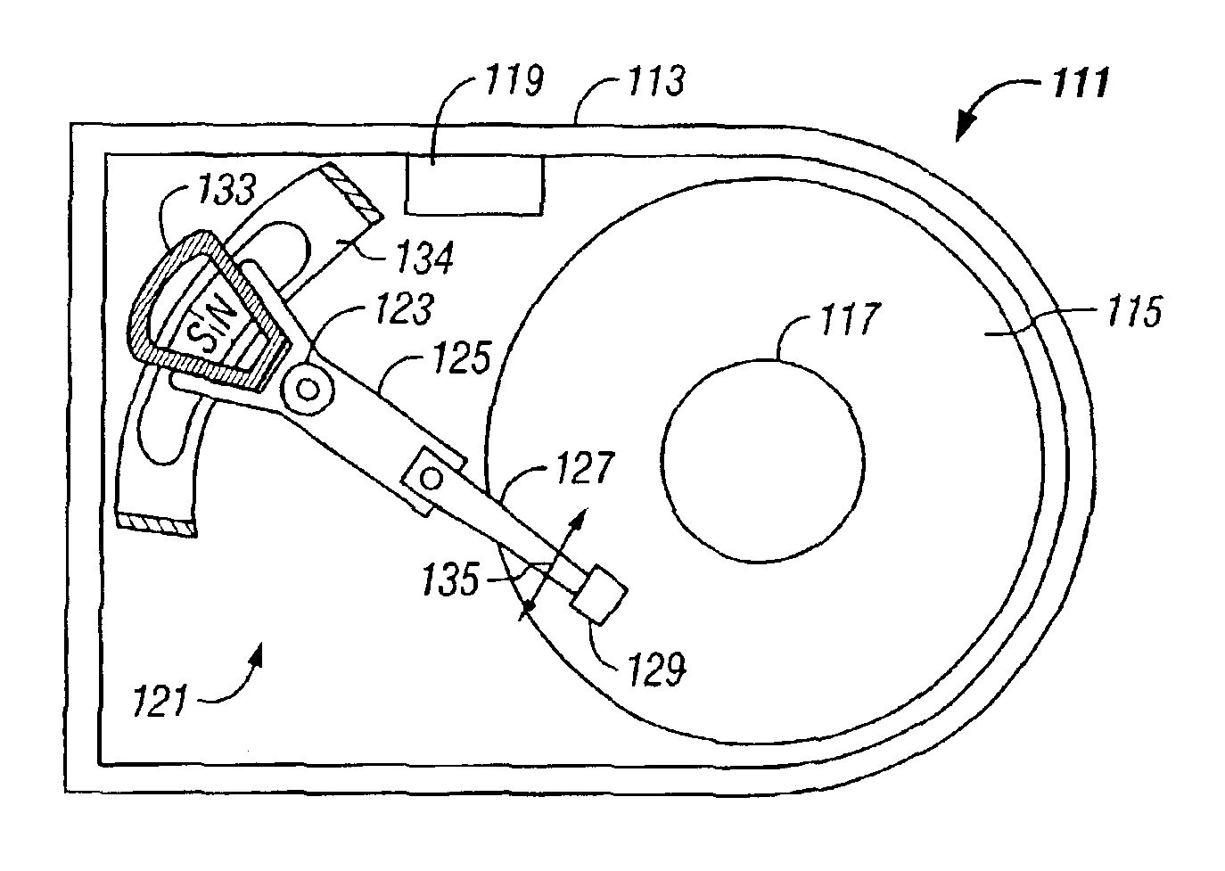
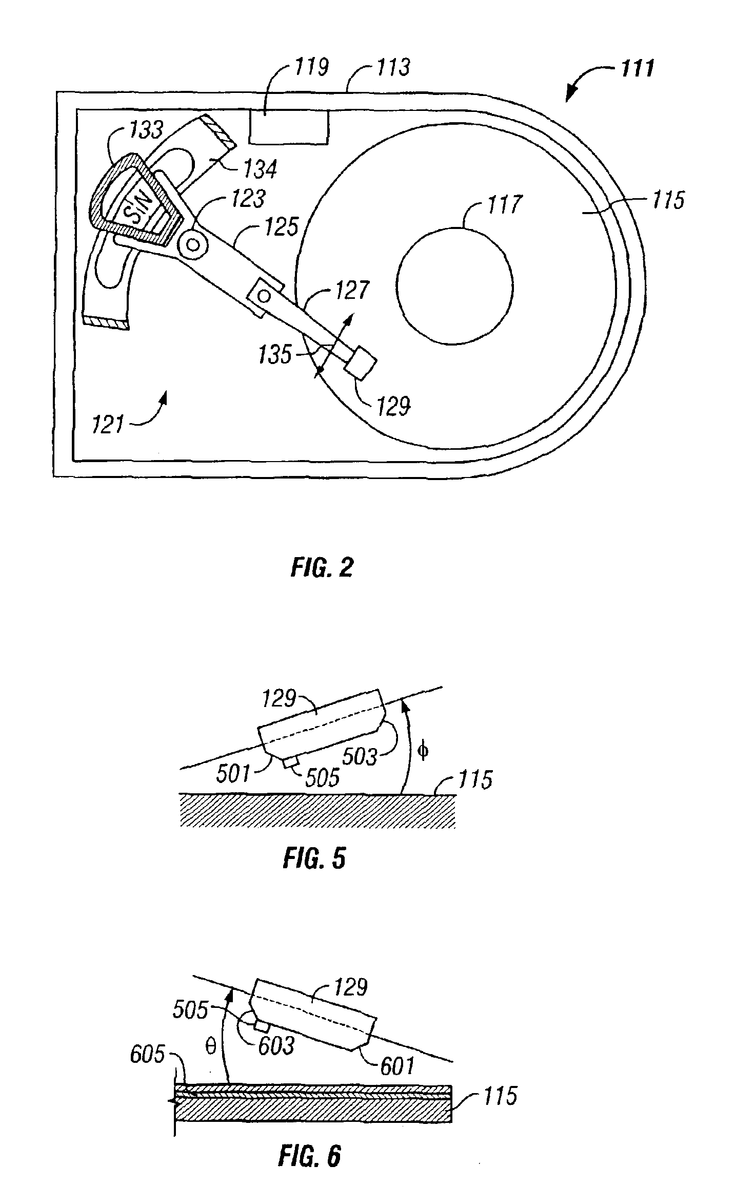
[0021]Referring to FIG. 2, a schematic drawing of one embodiment of an information storage system comprising a magnetic hard disk file or drive 111 for a computer system is shown. Drive 111 has an outer housing or base 113 containing a plurality of stacked, parallel magnetic disks 115 (one shown) which are closely spaced apart. Disks 115 are rotated by a spindle motor assembly having a central drive hub 117. An actuator 121 comprises a plurality of parallel actuator arms 125 (one shown) in the form of a comb that is pivotally mounted to base 113 about a pivot assembly 123. A controller 119 is also mounted to base 113 for selectively moving the comb of arms 125 relative to disks 115.

[0022]In the embodiment shown, each arm 125 has extending from it at least one cantilevered load beam or suspension 127. A magnetic read / write transducer or head is mounted on a slider 129 (shown schematically) and secured to a flexure that is flexibly mounted to each suspension 127. The read / write heads ...


PUM

PropertyMeasurementUnit
sizeaaaaaaaaaa
sizeaaaaaaaaaa
velocitiesaaaaaaaaaa

Abstract

A hard disk drive utilizes hard disks that recover the historically unused read / write space or real estate located in the load / unload zone. Approximately one-half of the load / unload zone is recovered and available for reading and writing operations by forming a first or radially outermost read / write track beginning immediately adjacent to the inner radial edge of the load / unload zone and proceeding radially inward from there to the conventional location of first tracks in the prior art. In another version of the invention, almost the entire load / unload zone is recovered and available for reading and writing operations by aligning the first track with the center of the load / unload zone and proceeding radially inward from there as described above. Both of these versions make significant additional surface area on the disk available where, in the prior art, no data was stored, thereby increasing the efficiency and storage capacity of the hard disk drive.

Description

BACKGROUND OF THE INVENTION[0001]1. Technical Field[0002]The present invention relates in general to improved utilization of disk storage space in a hard disk drive and, in particular, to an improved method and apparatus for recovering previously unutilized load / unload zone real estate on the disks of hard disk drives.[0003]2. Description of the Related Art[0004]Generally, a data access and storage system consists of one or more storage devices that store data on magnetic or optical storage media. For example, a magnetic storage device is known as a direct access storage device (DASD) or a hard disk drive (HDD) and includes one or more disks and a disk controller to manage local operations concerning the disks. The hard disks themselves are usually made of aluminum alloy or a mixture of glass and ceramic, and are covered with a magnetic coating. Typically, one to six disks are stacked vertically on a common spindle that is turned by a disk drive motor at several thousand revolutions...

Claims


Application Information

Patent Timeline
Patent Type & Authority Patents(United States)
IPC IPC(8): G11B21/22G11B5/54G11B21/12G11B5/738G11B5/60G11B20/10G11B20/12G11B20/18G11B21/10G11B21/21
CPCG11B5/54G11B21/12G11B21/22G11B21/10
Inventor SUK, MIKEGILLIS, DONALD R.
Owner WESTERN DIGITAL TECH INC
Learn More