Eureka AIR delivers breakthrough ideas for toughest innovation challenges, trusted by R&D personnel around the world.

Apparatus and method for compressing video information

a video information and apparatus technology, applied in the field of apparatus and methods for encoding and decoding video information, can solve problems such as prediction errors set, and achieve the effect of reducing the amount of data and efficient encoding of data representation

Inactive Publication Date: 2005-08-30
GEN DYNAMICS INFORMATION TECH
View PDF72 Cites 38 Cited by
  • Summary
  • Abstract
  • Description
  • Claims
  • Application Information

AI Technical Summary

Benefits of technology

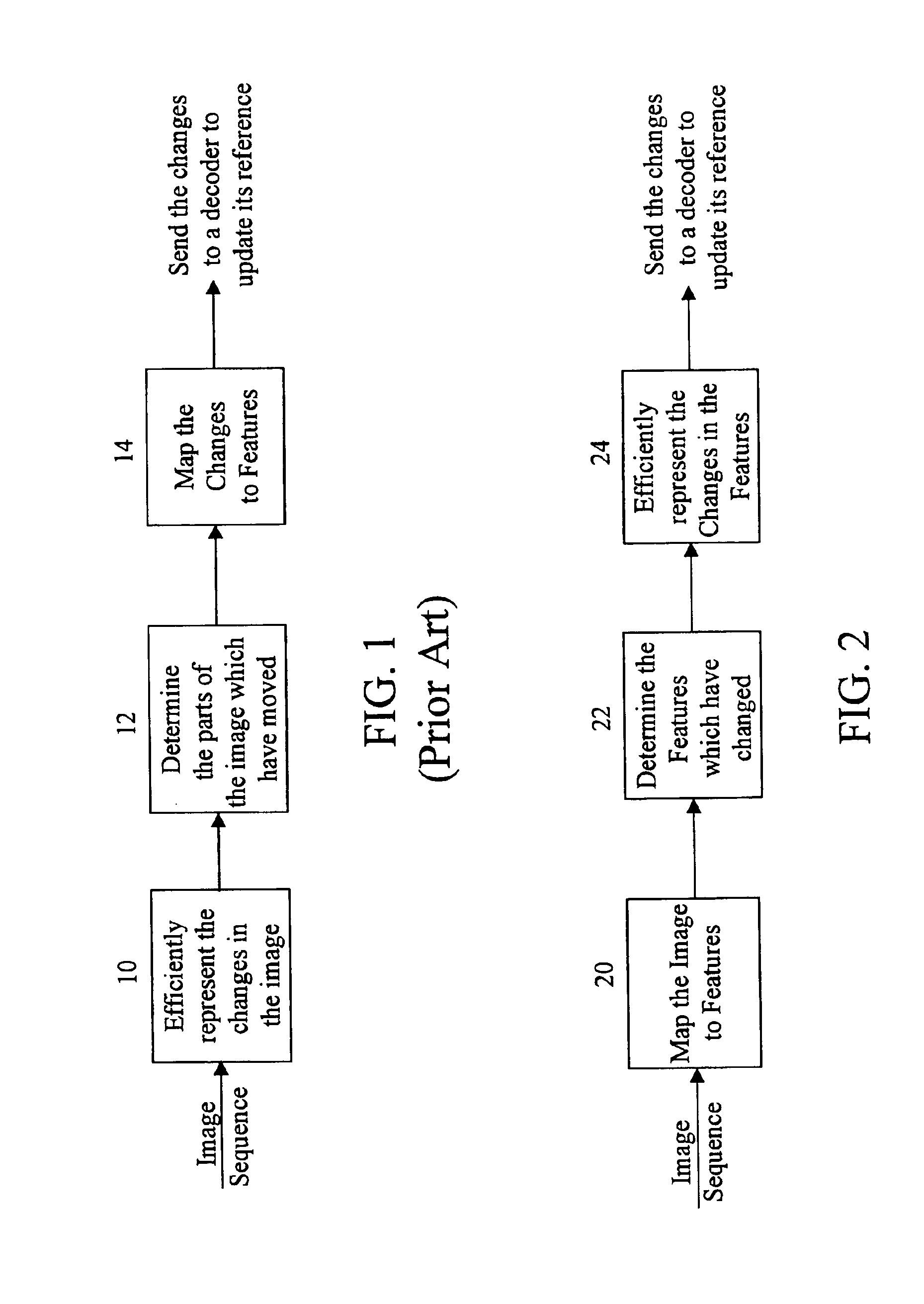
[0014]The subject invention is directed to a novel and unique apparatus and method for compressing data. More particularly, the present apparatus and method are adapted and configured to more efficiently encode data representing, for example, a video image, thereby reducing the amount of data that just be transferred to a decoder.
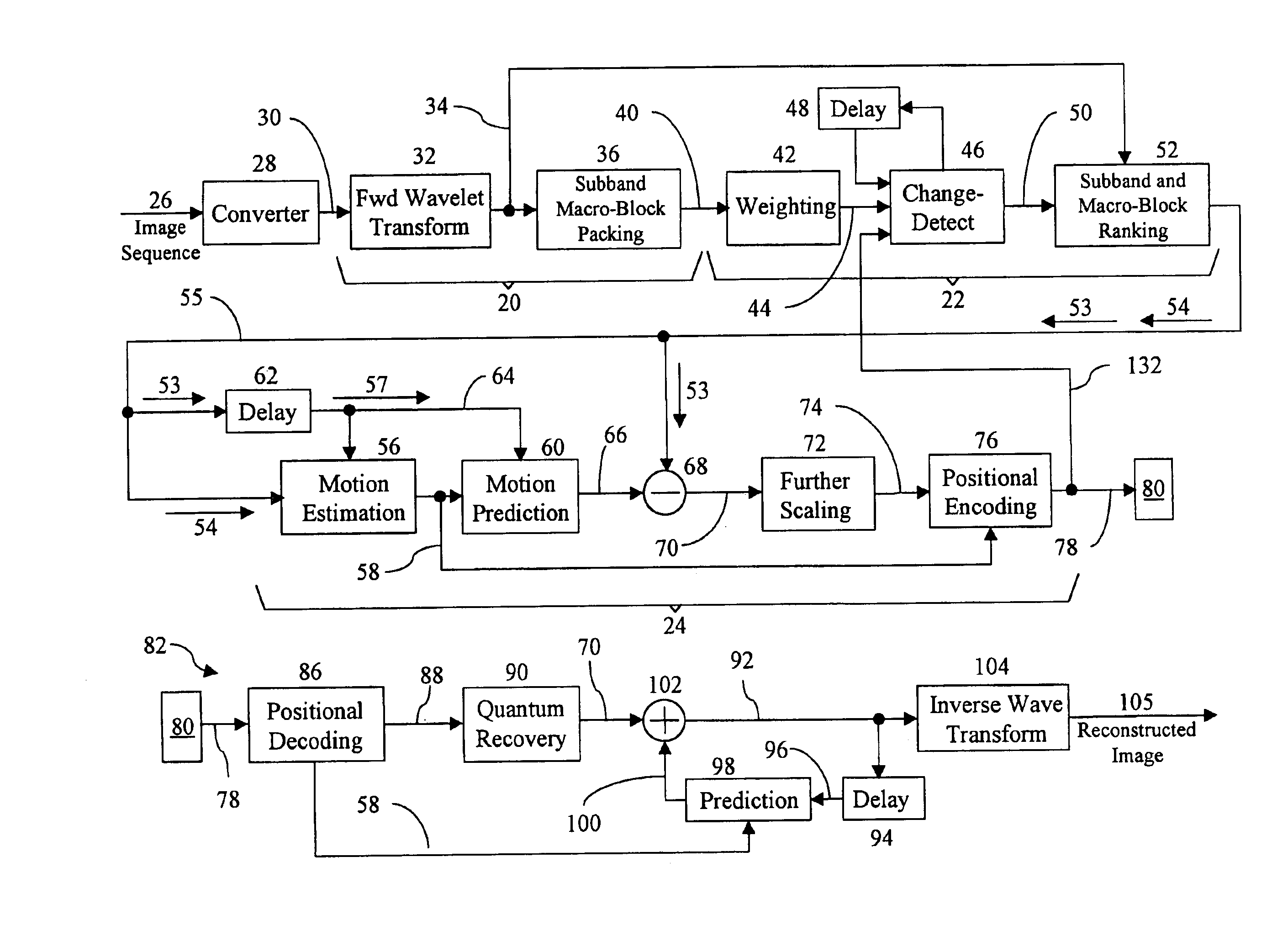
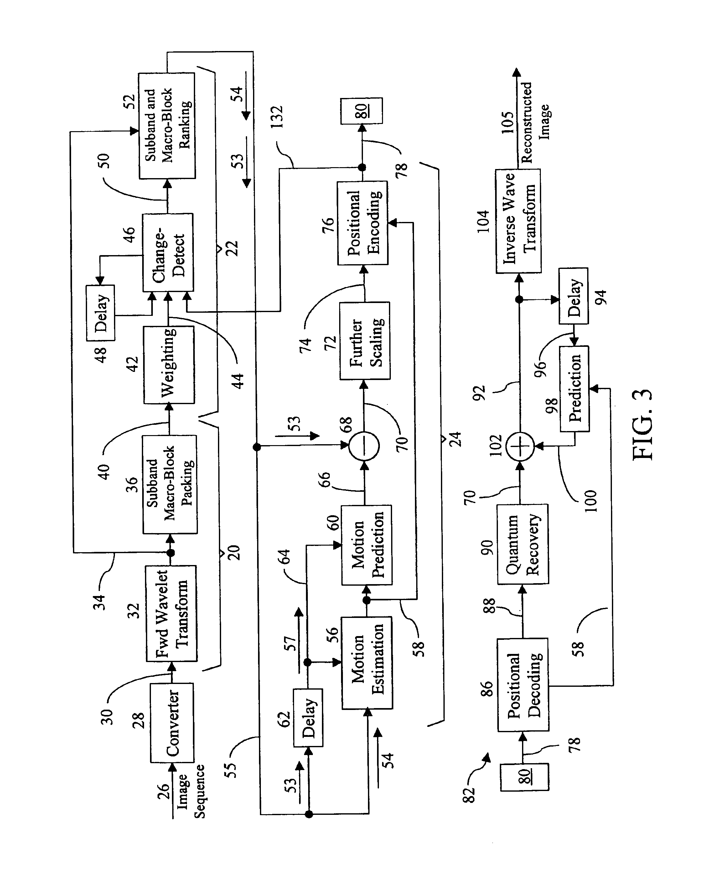
[0039]Also disclosed is an encoder apparatus for predicting changes between a sequence of frames in the transform domain. The apparatus includes a transformation device, having an input configured to receive a first and second frame of the sequence of frames, and further configured to generate therefrom a corresponding first and second collection of subbands that each support a set of transform coefficients. A motion compensation device, having an input coupled to the transformation device, is configured to receive the first and second collection of subbands, and further configured to efficiently represent differences between the first and second collection of subbands. Also included is a difference block having an input coupled to the transformation device and an input coupled to the output of the motion compensation device. The input received from the motion compensation device is subtracted from the second collection of subbands in the difference block, thereby generating a prediction errors.

Problems solved by technology

The prediction is subtracted from the second transform coefficient set resulting in a set of prediction errors.

Method used


Image

  • Apparatus and method for compressing video information
  • Apparatus and method for compressing video information
  • Apparatus and method for compressing video information

Examples


Embodiment Construction

[0059]An embodiment of the present invention provides an apparatus and method for compressing digital video signals using a limited precision transformation technique. The embodiment improves on conventional loss-less or lossy transform based techniques by motion compensating, e.g., estimating and predicting motion, in the transform domain, rather than in the time domain as in the prior art. In this manner, improved image quality can be achieved on less expensive hardware.

[0060]The term “motion compensation” is intended to be defined in its broadest sense. In other words, although motion compensation is often described and is illustrated herein as including motion estimation and motion prediction of a group of picture elements, it should also be understood to encompass, for example, rotation and scale. In addition, the term “motion compensation” may include, for example, simply generating data representing differences between two sets of data.

[0061]Compression efficiencies are gaine...


PUM


Abstract

A method and apparatus is disclosed for efficiently encoding data representing a video image, thereby reducing the amount of data that must be transferred to a decoder. The method includes transforming data sets utilizing a tensor product wavelet transform which is capable of transmitting remainders from one subband to another. Collections of subbands, in macro-block form, are weighted, detected, and ranked enabling prioritization of the transformed data. A motion compensation technique is performed on the subband data producing motion vectors and prediction errors which are positionally encoded into bit stream packets for transmittal to the decoder. Subband macro-blocks and subband blocks which are equal to zero are identified as such in the bit stream packets to further reduce the amount of data that must be transferred to the decoder.

Description

CROSS-REFERENCE TO RELATED APPLICATIONS[0001]This application claims priority to provisional application Ser. No. 60 / 066,638, filed Nov. 14, 1997, which is herein incorporated by reference.BACKGROUND OF THE INVENTION[0002]1. Field of the Invention[0003]The present invention relates generally to apparatus and methods for encoding and decoding video information. More particularly, the present invention relates to an apparatus and method for motion estimation and motion prediction in the transform domain.[0004]2. Background of the Related Art[0005]Due to the limited bandwidth available on transmission channels, only a limited number of bits are available to encode audio and video information. Video encoding techniques attempt to encode video information with as few bits as possible, while still maintaining the image quality required for a given application. Thus, video compression techniques attempt to reduce the bandwidth required to transmit a video signal by removing redundant infor...

Claims


Application Information

Patent Timeline
IPC IPC(8): H04N7/12H04N7/26H04N7/36
CPCH04N19/503H04N19/63H04N19/61H04N19/48H04N19/635H04N19/64H04N19/619H04N19/42
Inventor NGUYEN, TRUONG Q.ROSIENE, JOEL
Owner GEN DYNAMICS INFORMATION TECH
Why Eureka
Eureka Blog
Learn More