Apparatus, system and method for flip modulation in an impulse radio communications system

a radio communication system and apparatus technology, applied in the field of apparatuses, systems and methods for wireless communication, can solve problems such as inability to be utilized by other transmissions

Inactive Publication Date: 2005-08-30
ALEREON
View PDF15 Cites 137 Cited by
  • Summary
  • Abstract
  • Description
  • Claims
  • Application Information

AI Technical Summary

Benefits of technology

[0009]The present invention relates to apparatuses, systems and methods for modulation in an impulse radio communications system. The present invention also relates to apparatuses, systems and methods for transmitting and receiving modulated impulse radio signals. According to an embodiment, the present invention is directed to transmitting and receiving flip modulated im...

Problems solved by technology

In turn, this channel occupies spectrum space which, if inter...

Method used


Image

  • Apparatus, system and method for flip modulation in an impulse radio communications system
  • Apparatus, system and method for flip modulation in an impulse radio communications system
  • Apparatus, system and method for flip modulation in an impulse radio communications system

Examples


Embodiment Construction

[0060]

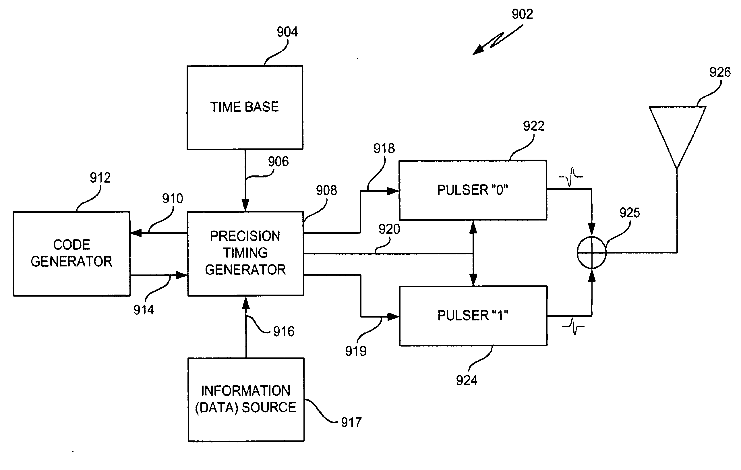
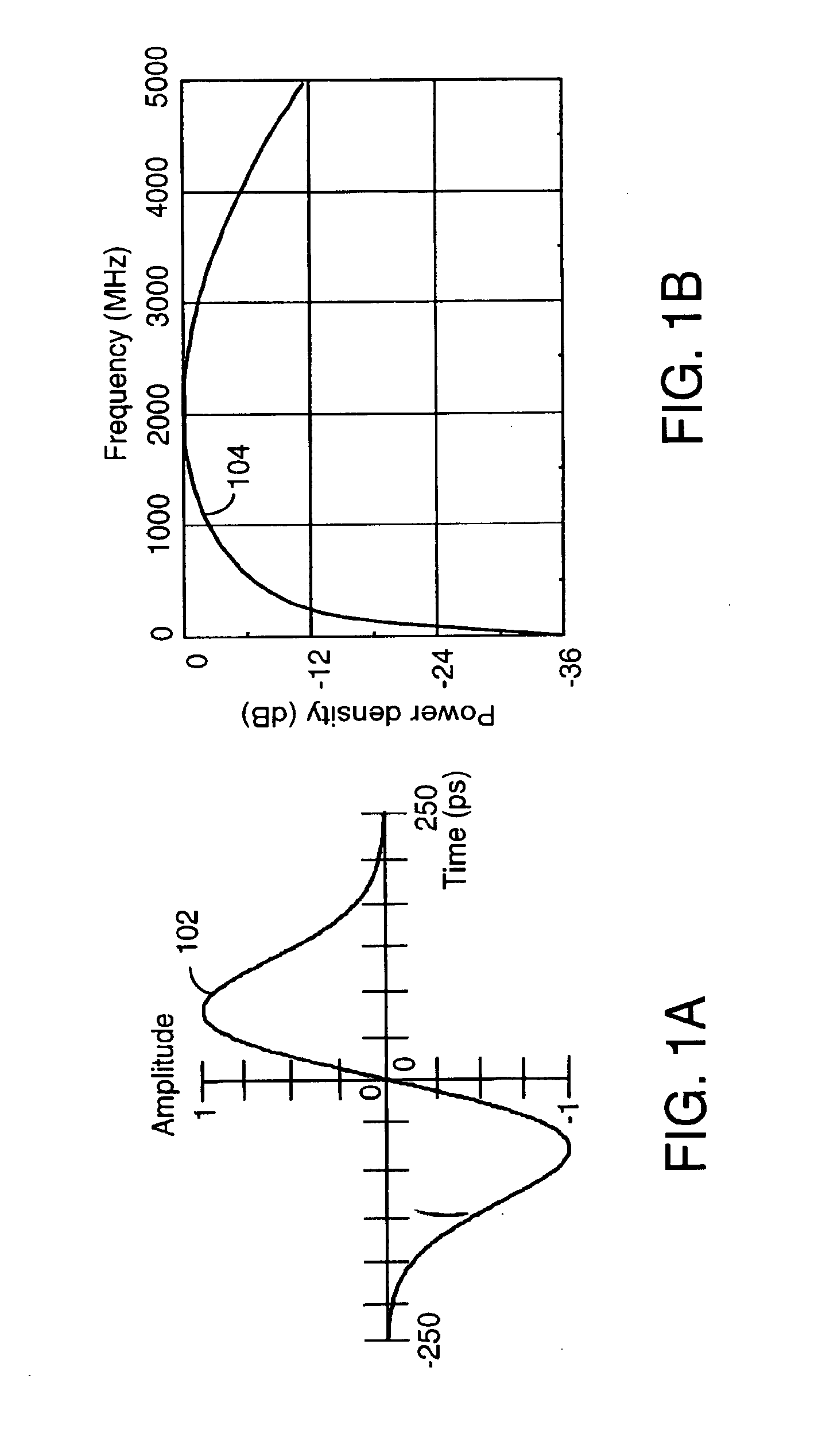
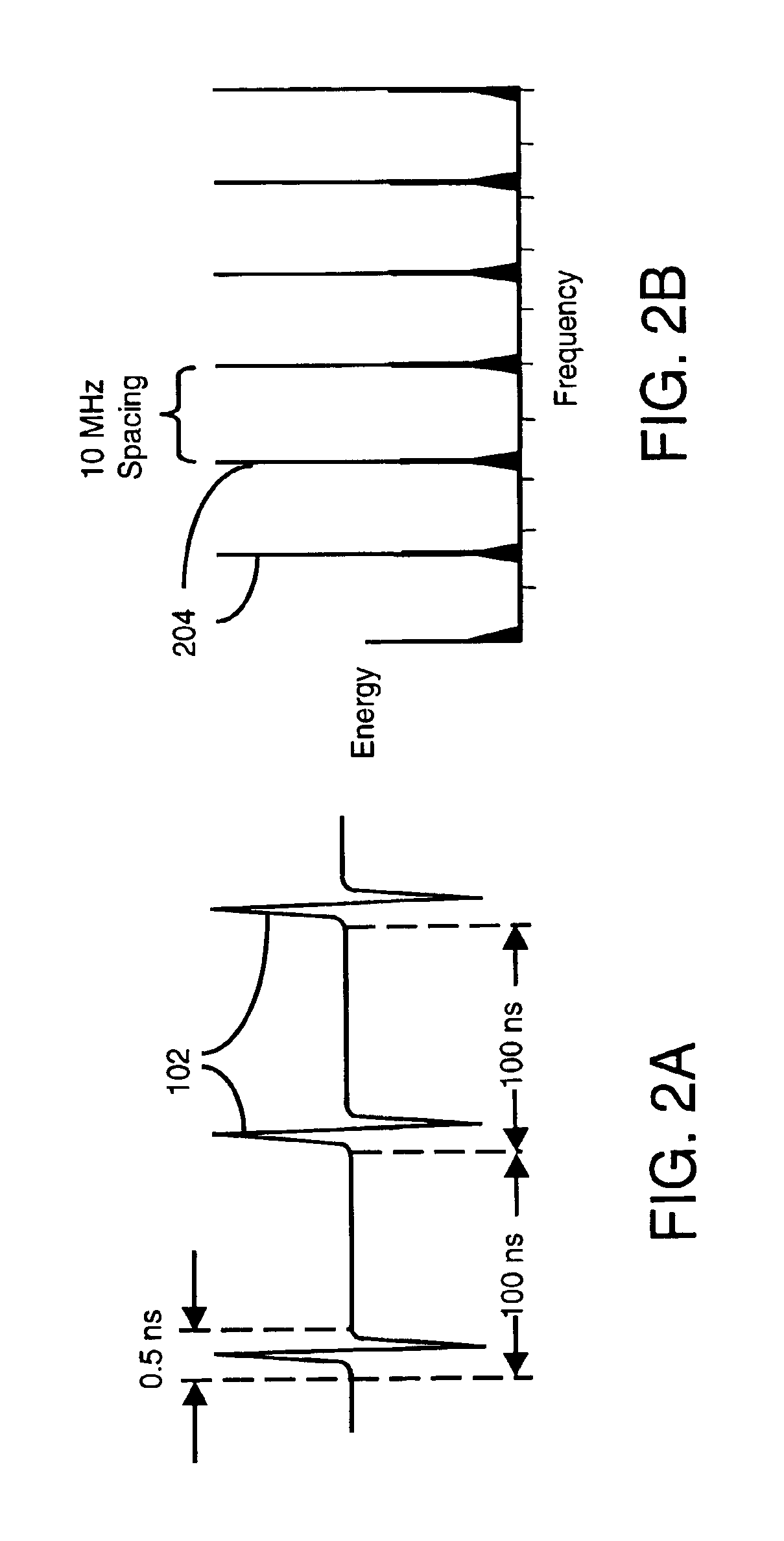
Table of ContentsI.Overview of the InventionII.Impulse Radio BasicsII.1.WaveformsII.2.Pulse TrainsII.3.Coding for Energy Smoothing and ChannelizationII.4.ModulationII.5Reception and DemodulationII.6.Interference ResistanceII.7.Processing GainII.8.CapacityII.9.Multipath and PropagationII.10.Distance MeasurementII.11.Exemplary TransmitterII.12Exemplary ReceiverIII.Preferred EmbodimentsIII.1.Flip ModulationIII.1.A.TransmitterIII.1.A.i.PulsersIII.1.A.i.a.Positive Polarity PulsersIII.1.A.i.b.Negative Polarity PulsersIII.1.A.i.c.Bi-Polar Polarity PulsersIII.1.A.i.d.On-Chip Bi-Polar Polarity PulserIII.1.A.ii.Alternative TransmitterIII.1.B.ReceiverIII.1.B.i.Correlation ProcessIII.1.B.ii.Data Path Signal Selector / InverterIII.1.B.iii.Max Value SelectorIII.1.B.iv.Illustrative ExamplesIII.1.B.v.Lock Loop FunctionIII.1.B.v.a.Lock Loop CorrelationIII.1.B.v.b.Lock Path Signal Selector / Inverter and Output SelectorIII.1.B.v.c.Alternative EmbodimentsIII.1.C.Use of a SubcarrierIII.2.Flip With Sh...


PUM


Abstract

Apparatuses, systems and methods for transmitting and receiving modulated impulse radio signals. An impulse radio receiver includes a time base, a precision timing generator, a template generator, a delay, first and second correlators, a data detector and a time base adjustor. The time base produces a periodic timing signal that is used by the precision timing generator to produce a timing trigger signal. The template generator uses the timing trigger signal to produce a template signal. A delay receives the template signal and outputs a delayed template signal. When an impulse radio signal is received, the first correlator correlates the received impulse radio signal with the template signal to produce a first correlator output signal, and the second correlator correlates the received impulse radio signal with the delayed template signal to produce a second correlator output signal. The data detector produces a data signal based on at least the first correlator output signal. The time base adjustor produces a time base adjustment signal based on at least the second correlator output signal. The time base adjustment signal is used to synchronize the time base with the received impulse radio signal.

Description

BACKGROUND OF THE INVENTION[0001]1. Field of the Invention[0002]The present invention relates generally to apparatus, systems and methods for wireless communication. More particularly, the present invention relates to apparatuses, systems and methods for modulation in an impulse radio communication system. The present invention also relates to apparatuses, systems and methods for transmitting and receiving modulated impulse radio signals.[0003]2. Related Art[0004]The radio transmission of both analog and digital communications intelligence has normally been effected by one of two methods. In one, referred to as an amplitude modulation, a continuous sinusoidal radio frequency carrier is modulated in amplitude according to an intelligence or communications signal. When the amplitude modulated signal is received at a receiving location, the reverse process (that is, demodulation of the carrier) is effected to recover the intelligence. The other method employs what is termed frequency m...

Claims


Application Information

Patent Timeline
IPC IPC(8): H04B1/69H04B1/7095H04B1/7163H04B1/717H04B1/7176H04B1/7183H04L25/49
CPCH04B1/7095H04B1/7174H04B1/71632H04B1/7176H04B1/7183
Inventor FULLERTON, LARRY W.RICHARDS, JAMES L.COWIE, IVAN A.DICKSON, DAVID M.BRETHOUR, VERNON R.JETT, PRESTON
Owner ALEREON
Why Eureka
Try Eureka