Left hand right hand invariant dynamic finger positioning guide

a technology of finger positioning guide and left hand, applied in the field of fingerprint scanners, can solve the problems of high cost of fingerprint attendant training to assist users in the positioning of their fingers, severe limitations in the deployment of these systems, and inability to achieve the effect of high system accuracy and low cos

Inactive Publication Date: 2005-08-30
QUALCOMM INC
View PDF9 Cites 88 Cited by
  • Summary
  • Abstract
  • Description
  • Claims
  • Application Information

AI Technical Summary

Benefits of technology

[0012]An overall improvement can be made to all live scan fingerprint readers by providing the automatic guide in accordance with the present invention for properly positioning the finger horizontally, vertically, and without rotation. Doing so will ensure that the user's finger will be in the optimum position of the fingerprint platen, without distortion, thereby enabling the highest possible system accuracy. Furthermore, the system is able to do this without the help of the user, an attendant, or a display such as a PC Monitor. This makes the system user friendly and low cost, thereby enabling the use of these devi

Problems solved by technology

Using an attendant to assist the user and providing visual feedback of the image severely limits the deployment of these systems.
For example, for most commercial applications the cost of a trained fingerprint attendant to assist the user in the positioning of their finger is prohibitive.
Techniques to train the users on the proper placement of the finger have been tried but generally do not work.
Even if they did, adding a PC Monitor near the fingerprint scanner to provide positional feedback also raises the cost of the system beyond what can be tolerated by most commercial applications.
First, the user, by seeing the finger on the PC Monitor, will tend to slide their finger into position until it is properly located. Because of the friction between the skin and the platen, the sliding effect introduces distortion of the fingerprint, thereby introducing errors in the identification/verification process.
Second, many live-scan fingerprint readers cannot produce an image of the finger fast enough to give the user the instantaneous feedback they need to guide them. For these scanners, the use of a dis

Method used


Image

  • Left hand right hand invariant dynamic finger positioning guide
  • Left hand right hand invariant dynamic finger positioning guide
  • Left hand right hand invariant dynamic finger positioning guide

Examples


Embodiment Construction

, when read in conjunction with the accompanying drawings, is in such full, clear, concise and exact terms as to enable any person skilled in the art to which it pertains, or with which it is most nearly connected, to make and use the invention.

BRIEF DESCRIPTION OF THE DRAWING FIGURES

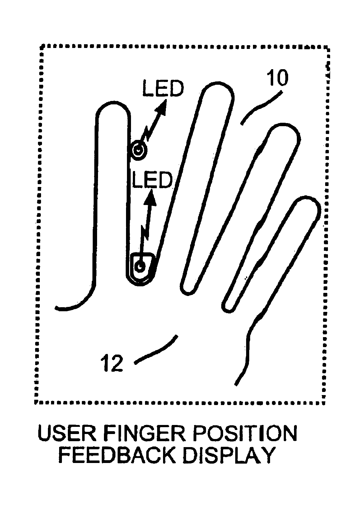
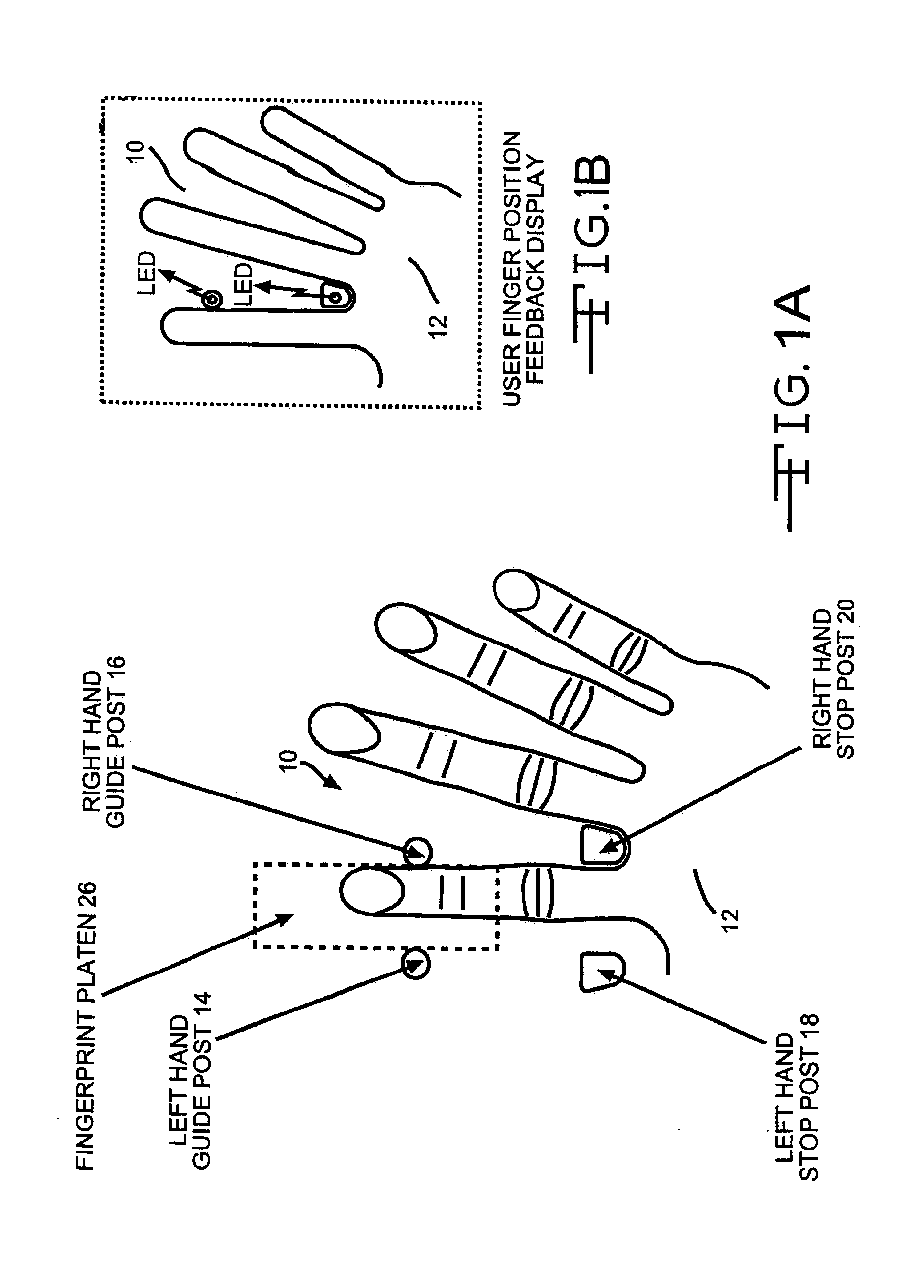
[0015]FIGS. 1A and 1B are diagrammatic views illustrating the automatic finger guide according to the present invention;

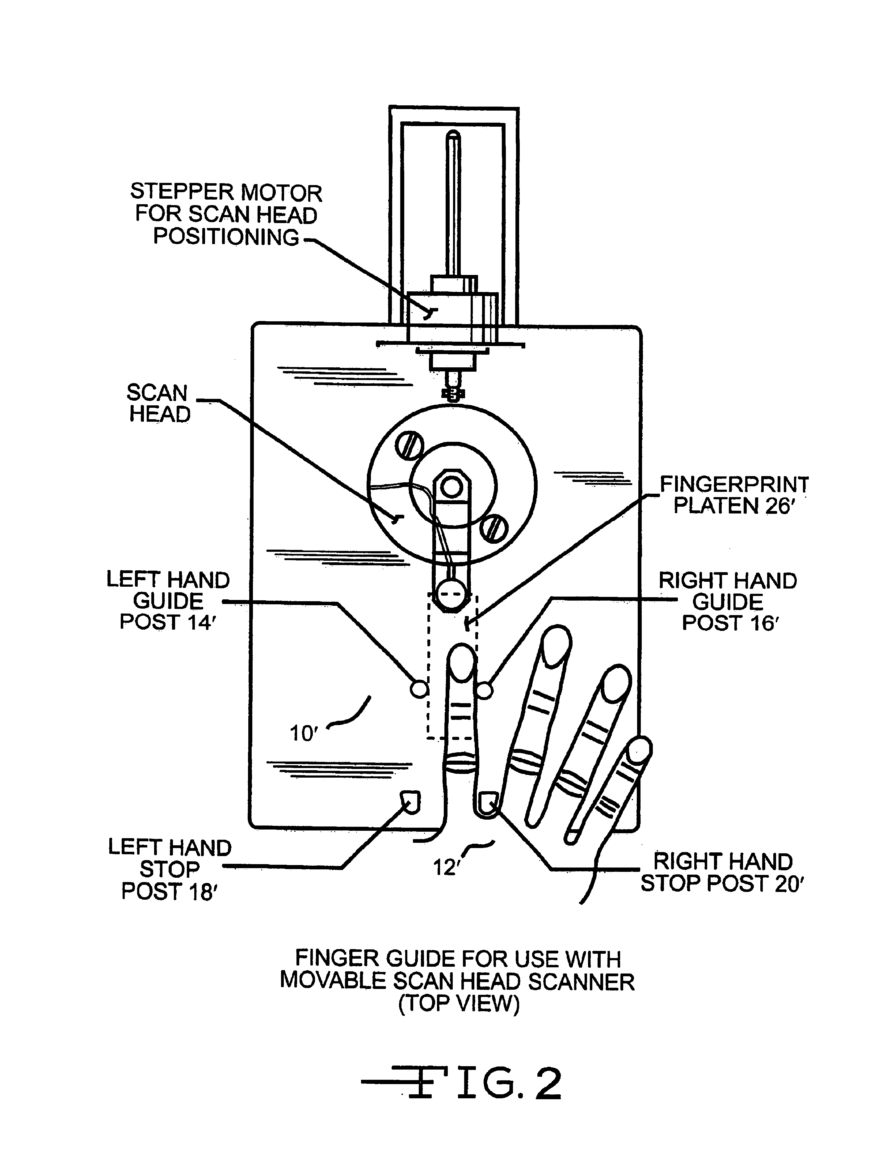
[0016]FIG. 2 is a top plan view, partly diagrammatic, of the finger guide of the present invention for use with one type of scanner;

[0017]FIG. 3 is a side elevantional view, with parts removed, of the apparatus of FIG. 2;

[0018]FIG. 4 is a perspective view of the finger guide of the present invention for use with another type of scanner;

[0019]FIG. 5 is a diagrammatic view further illustrating an alternative form of guide post of the finger guide of the present invention;

[0020]FIGS. 6A-6C are diagrammatic views illustrating alternative finger sensing arrangements for use in the finger gu...


PUM


Abstract

An automatic finger guide for fingerprint scanners includes active scan area on the scanner surface upon which one finger rests and a non-active scan area on the scanner surface on which the other finger(s) rest to provide stability, a stop post to indicate how far forward to place the hand, a guide post to assist in positioning the finger left to right or right to left as the case may be, sensors on the post to provide feedback to the user to when the hand is properly in place and to determine the position as to where the finger comes to rest on the active scan area.

Description

CROSS REFERENCE TO A RELATED APPLICATION[0001]Applicants hereby claim priority based on Provisional Application No. 60 / 153,180 filed Sep. 10, 1999 and entitled “Left Hand Right Hand Invariant Dynamic Finger Positioning Guide” which is incorporated herein by reference.BACKGROUND OF THE INVENTION[0002]Inkless fingerprint scanners, also known as live scan fingerprint readers or biometric devices, have been widely used for many years. These systems obtain an image of the fingerprint without the use of inks. Once an image is acquired, it is then processed and an identification or verification of the individual's identity is made.[0003]Many different techniques have been used to obtain an image of the finger including optical scanners, thermal scanners, capacitive scanners, E-field sensors, ultrasonic scanners, and many more. Each uses a different modality or technique to image the same physical characteristic; the ridge structure of the finger. Each claim to have certain advantages over ...

Claims


Application Information

Patent Timeline
IPC IPC(8): G06K9/00G06V40/13
CPCG06K9/00013G06K9/00919G06V40/13G06V40/63
Inventor SCHNEIDER, JOHN K.GOJEVIC, STEPHEN M.KEENEY, FRANK W.KIEFER, FREDERICK W.
Owner QUALCOMM INC
Why Eureka
Try Eureka