Removable eyewear member

a technology of eyewear and lens, applied in the field of eyeglasses and sunglasses, can solve the problems of lens eyewear, extreme restrictions, and wide view afforded by singular lenses, and achieve the effect of improving adjustability

Inactive Publication Date: 2005-09-06
LINDAHL ARTHUR CHARLES
View PDF49 Cites 71 Cited by
  • Summary
  • Abstract
  • Description
  • Claims
  • Application Information

AI Technical Summary

Benefits of technology

[0024]An alternative of the previously described embodiment is had where the structure for completely segregating and separating the individual eyewear member sections from each other further includes a telescoping interconnection in order to provide enhanced adjustability. A further variation of this design is seen as a further embodiment in which the mechanism of separation further includes an interlocking structure. Another embodiment of the structures as described above involves a design where the mechanism for separation comprises a removable angular projection member. In another embodiment, the mechanism for separation further comprises a magnetic attraction member.
[0025]A further embodiment provides for easy removal and installation of an eyewear member support structure relative to the eyewear. A further embodiment is obtained by the use of at least one U-shaped or angled projection member connected to the detachable eyewear member with each angled projection member configured to engage the eyewear. In a further embodiment, at least one of the U-shaped members described are configured to be adjustable relative to the eyewear member and the eyewear it engages so as to achieve usage of the eyewear member on a greater number of different designs and shapes of eyewear. In yet another embodiment related to the Angled projection member, the Angled projection member is modified by being removable from the eyewear member altogether. This configuration allows the user to achieve usage of the eyewear member on a greater number of different designs and shapes of eyewear by inter-changing different shapes or lengths of the Angled projection member for maximum utilization.

Problems solved by technology

Thus the wide view afforded by the singular lens comes at the expense of having a wide open space between the peripheral edge of the lens or lens support structure and the user's face.
The same issues occur in two lens eyewear in the wide open space between the lens & user's face.
Goggles, which are different from conventional non-goggle eyewear, are considered to be extremely restrictive, as they typically hug and seal with the face of the user to isolate the eyes as much as possible from wind and debris, but they are typically used only in extreme conditions and not, for example to walk upon the beach or to play volleyball, two instances where a more relaxed, lightweight and non-constricting eyewear is the general preference.
Also, sunglass use is limited for some people who require an extreme structure around the head for certain sports, or due to the fact that they have had laser surgery and require greater protection for their eyes.
They could not effectively wear their normally extremely restrictive sports eyewear at all times without suffering a great deal of discomfort.
Extremely restrictive head wear can work well, but generally for only specific situations, such as riding a motorcycle or skiing.
However, they fall short of being practical when used generally as a sunglass or spectacle, driving a car, or having lunch at an outdoor cafe.
This is due to their being large, bulky, hot, and not very stylish for such activities.
Although more stylish, these fixed seal sunglasses fall short of an ultimate solution for an all around eyewear product.
This is because the user is left to using the hot, restrictive eyewear all the time due to the inability to attach and detach a sealing member at times when desired.
The attempts to ventilate the lens support structures of these fixed seal, extremely restrictive sunglasses works adequately with high motion activities, but does not make them less hot at times when there is no air circulation going through the ventilating areas such as when driving in a car.
Also, due to the rigid nature of eyewear lens support structures, and the many variances of the specific contour of the facial region surrounding the eyes of the user, certain users are left with a generally poor fit and incomplete sealing using a fixed seal with a given configuration, and which lacks customizability.
Also upon breakdown of the sealing structure for a fixed seal extremely restrictive sunglasses, the user is left with the inability to easily replace their sealing structure, virtually eliminating the total benefits of the product they had purchased.
Even where the enclosure extends across the area adjacent both eyes, extremely restrictive eyewear can still generally restrict the view of the user.
In terms of usage, a user is faced with having to buy both extremely restrictive eyewear and conventional sports glasses, and to use the appropriate eyewear depending upon circumstances.
Where debris is severe enough, such extremely restrictive eyewear are worn at the sacrifice of an expanded viewing angle, more heavily structured and bulky.
Where conventional open sports eyewear are worn, the user suffers the debris, particularly wind and dust, which may enter the eyes behind the lenses.
In addition, conventional sports eyewear, by having a significant gap on the face, even where the gap between the bottom of the lens and the face surrounding the eyes is low on the face, admits significant amounts of light.
Where the user gazes down, there will be a sudden change in light levels, which can both annoy the user and stress the user's eyes.
In some cases specialized ventilation ports are formed in the side walls of the lens support structures, but they are not always located properly or structured to provide adequate ventilation.
Even where adequate ventilation is provided, the such extremely restrictive eyewear do not provide a comfortable fit.
Lack of comfortable fit is not an acceptable tradeoff for durability and long usage life.
The seal used in conventional extremely restrictive eyewear is less able to withstand vigorous use, and tends to break down over a relatively short period of time.
The seal break down usually occurs far short of the full use life.
Apart from the abovementioned sports eyewear which may have a huge opening, especially at the bottom of a user's eyes, there is also the problem generally found in conventional eyeglasses, spectacles, and many sunglasses inherently do not have a close fit with the user's face.
This gap area, at times, can be annoying and can even be dangerous and life threatening, and more than simply high speed sports activities, side gusts of wind are provided with an even easier entrance and exit.
The annoyance can be due to the entry of wind, dust, water and light to the user's eyes.
The level of light to one's eyes can also be annoying.
For example, when the sun is shining brightly and a user is playing golf, the sun can have a blinding affect making it difficult for the user to make a golf shot.
Entry of water can also he annoying when engaged in some water sports, such as boating and kayaking.
The gap area becomes dangerous, for example, when bodily fluids from a patient with a communicable disease in a medical situation comes into contact with the eyes of the medical practitioner.
Entry of blood into the eyes from an aids patient could be life threatening.
However, using of these type of eyewear structure is highly deficient in reducing particulates from entering the eye region, when adapted for use in a variety of industrial safety eyewear, eyewear for swimming, motorcycle riding, skiing and the like.
A similar deficiency arises using most conventional sunglasses and eyewear which have temple members.

Method used


Image

  • Removable eyewear member
  • Removable eyewear member
  • Removable eyewear member

Examples


second embodiment

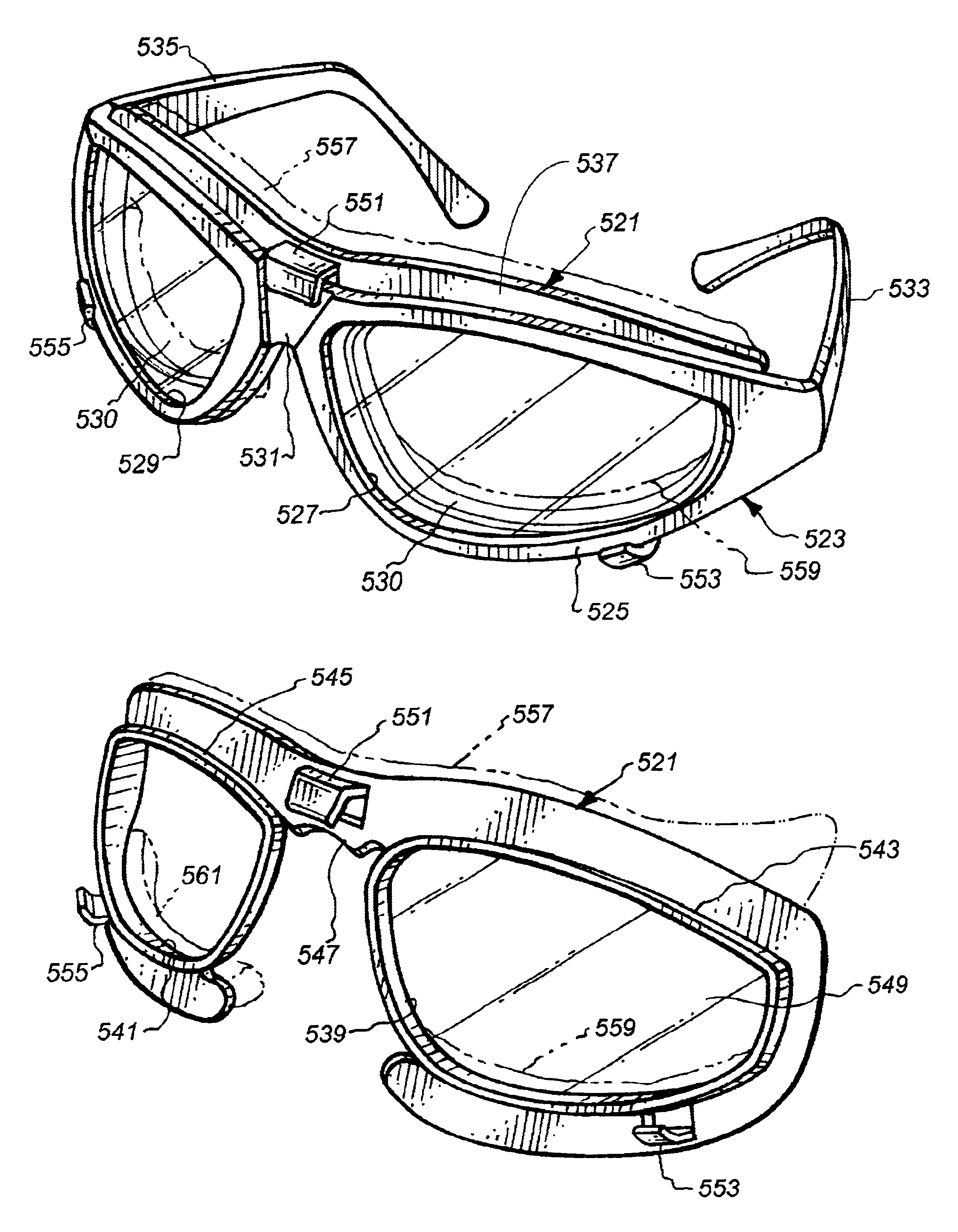
[0165]Referring particularly to FIG. 45 of the drawings, there is shown the second embodiment as an eyewear member 565. Like numerals have been utilized for like parts. However, the eyewear member 565 does not include the shaped angled projection member 551 but does include the shaped angled projection members 553 and 555. The eyewear member 565 is separated into two substantially equal parts with enlarged opening 539 being located separate from the enlarged opening 541. There may be certain situations in which the user may desire to use only one of the enlarged openings 539 or 541, and in that situation, the eyewear member 565 could be utilized. The eyewear member 5651 is broken in the area of the bridge 547 and has a pair of rounded members 567 and 569. The rounded members 567 and 569 can be interconnected together by a sleeve 571 which telescopingly connects between the rounded members 567 and 569. By using the sleeve 571, the user can achieve a structure which is basically simil...

sixth embodiment

[0169]Referring particularly to FIG. 49 of the drawings, there is shown a sixth embodiment, seen as an eyewear member 595. Again, like numerals are utilized to refer to like parts. The eyewear member 595 constitutes a thin walled eyewear member structure with the right side of the eyewear member 595 being bent upwards forming bent end 597 and the left side of the eyewear member being similarly bent inward forming bent end 599. The forming of bent ends 597 and 599 are also similarly formed with respect to the manner in which the basic support structure of the eyewear members 521, 565, 573, 577 and 581. The eyewear member 595 could be impregnated with a magnetic material which could be used to hold the eyewear member 595 to the eyeglasses 523 where the eyeglasses 523 were made of ferromagnetic material. However, eyewear member 595 could also include small bar magnets imbedded within the structure of the eyewear member 595 eyewear member 521. The eyewear member 595 could also be constr...

seventh embodiment

[0171]Referring particularly to FIG. 50 of the drawings, there is shown a seventh embodiment as a eyewear member 607. The eyewear member 607 is basically similar to the eyewear member 595 with the exception that the nosepiece sidewalls 601 and 603 have been removed, but where the vertically expanded portions 605 remain. Some users may prefer the more open configuration of the eyewear member 607 as opposed to an embodiment where the enlarged openings 539 and 541 are completely enclosed, as is shown for eyewear member 595.


PUM

PropertyMeasurementUnit
angleaaaaaaaaaa
angleaaaaaaaaaa
sizeaaaaaaaaaa

Abstract

Eyewear member includes a structure for fitting peripherally on or around or behind lens and structure of conventional eyewear. Interfitting structure ranges from sealing segments to eyewear members which may attachably engage or simply interfit behind conventional eyewear. The eyewear members enables conventional eyewear to form a closer fit with the face of the user to protect the person's eyes from wind, water and foreign material. All embodiments contemplate selectable removabilty, replace ability and interchangeability.

Description

[0001]This application is a continuation-in-part of application Ser. No. 09 / 352,898, filed Jul. 13, 1999 now U.S. Pat. No. 6,282,772, by the present inventor, entitled SPORTS EYEWEAR WITH DETACHABLE GOGGLE MEMBERS.FIELD OF THE INVENTION[0002]The field of this invention relates to eyeglasses and sunglasses and more particularly to improved removable eyewear members for eyeglasses and sunglasses to broaden their usage so as to substantially deflect at least one of light, dust, liquid or debris from entering into the eye region which occurs through the gaps between the face and the eyeglass or sunglass, as an improved elemental deflecting system.BACKGROUND OF THE INVENTION[0003]Conventional sports & safety eyewear currently exist which allow the user a wide angle of view. This particular type of eyewear is typified by a singular or two lenses which extends from the outside of one of the wearer's eyes and extends across to the outside of the other of the wearer's eyes, and only partiall...

Claims


Application Information

Patent Timeline
Patent Type & Authority Patents(United States)
IPC IPC(8): A61F9/02G02C11/00C03B8/02G02C1/00G02C1/06G02C9/00G02C11/02G02C11/08
CPCA61F9/025A61F9/026A61F9/029G02C1/06G02C9/00G02C11/08A61F2009/021G02C2200/02
Inventor LINDAHL, ARTHUR CHARLES
Owner LINDAHL ARTHUR CHARLES
Why Eureka
Try Eureka