Tension measured fishing line bite detector alarm

a detector and tension measurement technology, applied in fishing, other angling devices, animal husbandry, etc., can solve the problems of ineffectiveness, inconvenient operation, and high wiring costs, and achieve the effect of quick and efficient connection and disconnect, simple and effective technology, and effective resistance to false alarm signals

Inactive Publication Date: 2005-09-06
MICHAEL JAMES CAMERON
View PDF12 Cites 16 Cited by
  • Summary
  • Abstract
  • Description
  • Claims
  • Application Information

AI Technical Summary

Benefits of technology

[0031]Our invention comprises an innovated, compact, and light weight battery powered bite detector alarm, that quickly and efficiently connects to and disconnects from a rod and the line from its reel, and moreover effectively capable of providing resistance against false alarm signals due to water conditions, the movement of a live bait fish on a fishing line, or when the fishing line is being cast from a reel, and making it necessary to install the fishing line to the bite detector alarm only once during the course of the day or night fishing activity. The structure and mechanism design of our bite detector alarm, utilizes simple and effective technology improving on the imperfections mentioned above, experienced by these type of devices in the past.

Problems solved by technology

However, they suffer from imperfections such as being bulky, heavy, or fragile, and are made from numerous parts making attaching to and removing from the fishing rod a discouraging task, some have been designed so that the fishing line at all times must pass through some component while retrieving the fish without any tension relief to that component, or designed so that the fishing line falls out of a component every time a fish strikes and has to be reinserted, or designed so that the components have to be turned off or back on, or readjusted every time a fish is caught.
Others are electrically designed requiring expensive wiring, with certain electronic designs requiring expensive components, all cases mentioned above either being so elaborate that they are too costly for the average angler, or just ineffective.

Method used


Image

  • Tension measured fishing line bite detector alarm
  • Tension measured fishing line bite detector alarm
  • Tension measured fishing line bite detector alarm

Examples


Embodiment Construction

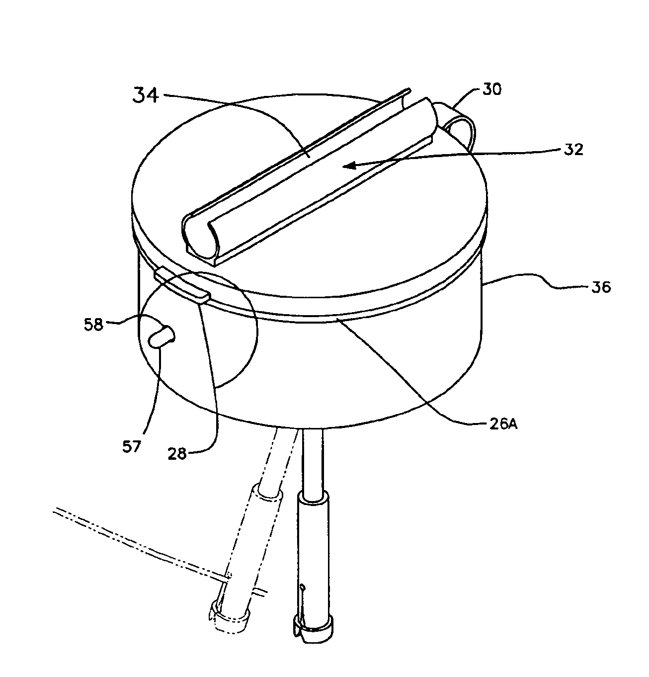
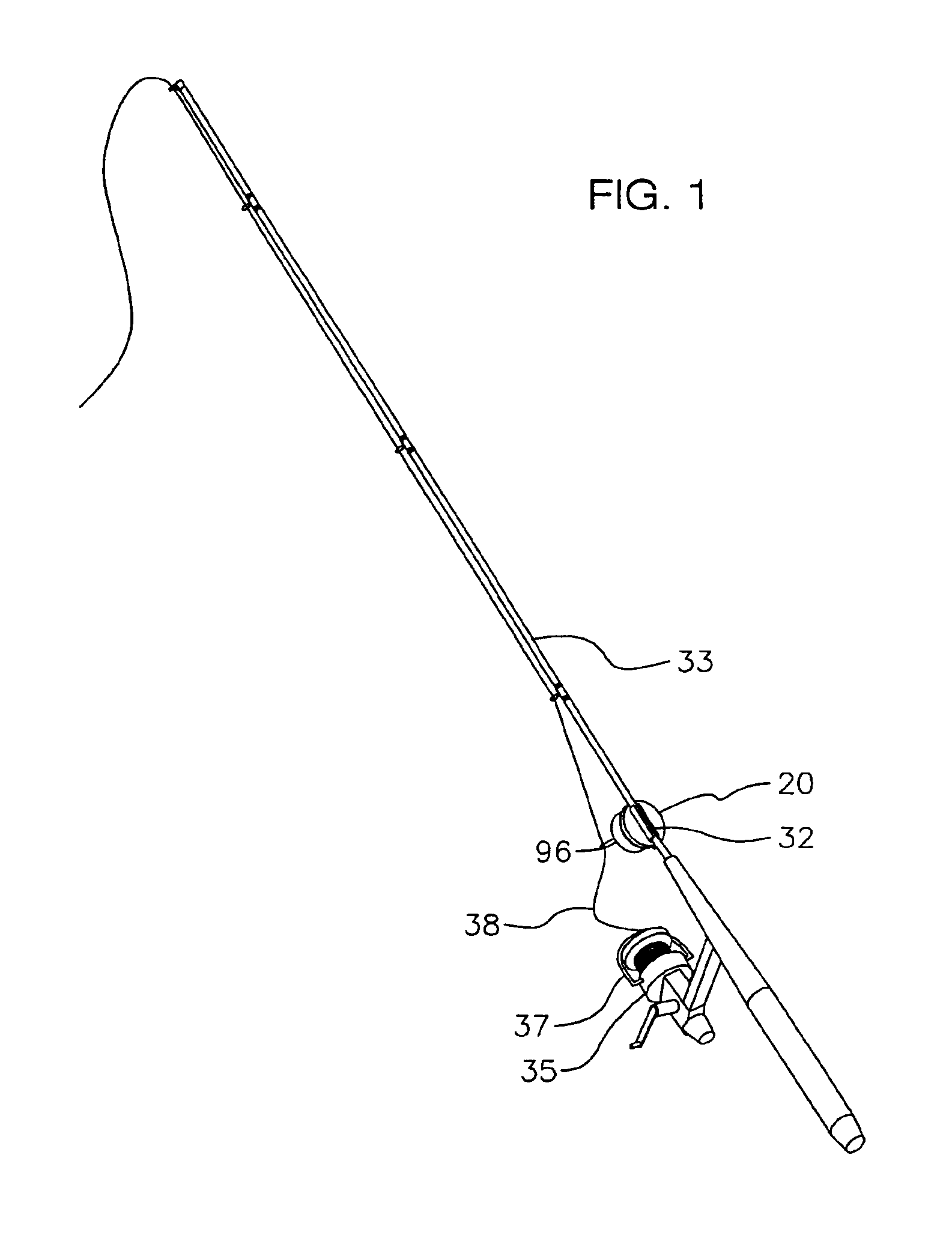
[0119]FIGS. 1, 2, 4, 9, and 10 show a bite detector alarm 20 of the current invention.

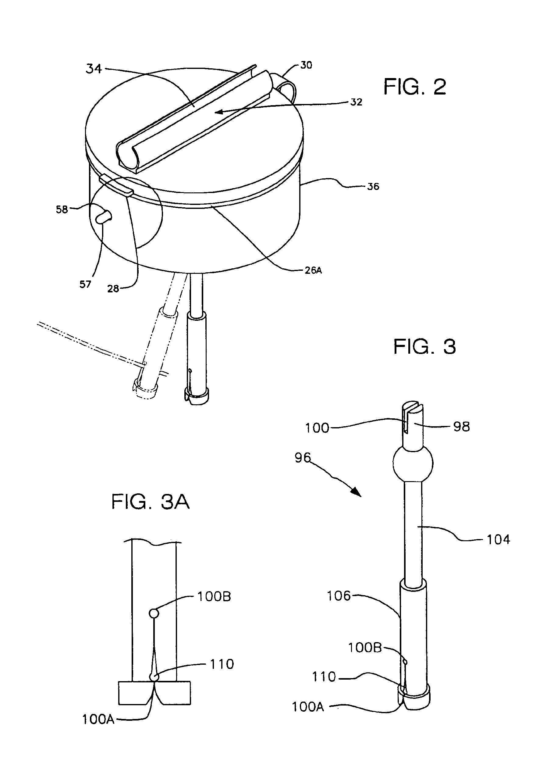
[0120]Referring FIG. 3, an actuator arm 96 is shown that is a solid cylindrical injection molded piece comprising, a slotted stem section 98, having a top slot 100 molded horizontally across the center of stem section 98 approximately 90 degrees in relation to a bottom slot 100A, a variable sized slit 110, and a line hole 100B, all molded within a slotted bottom section 106. As shown in FIG. 10, section 98 extends downward into approximate top center of a spherical pivot ball section 102, a mid arm section 104 extending extends downward from approximate bottom center of section 102 and transitions to section 106 (see FIG. 3). As shown in FIG. 3A, slot 100A comprises rounded sides, upwardly tapering until touching together and transitioning to slit 110, and slit 110 upwardly tapering and transitioning to hole 100B. In the preferred embodiment, a lathe turned actuator arm made of pomalux, acetyl copo...


PUM


Abstract

A battery powered fishing line bite detector alarm producing visible and / or audible alarm signals is disclosed. An arm, installed within the alarm, integrally connects to a modified leaf on-off switch. The alarm attaches to a fishing rod in front of a fishing reel mounted on the rod. Fishing line is threaded into the arm and adjusted such that slack is provided between the rear of the alarm and the front of the reel thereby allowing forward arm movement. The fishing line is further inserted until desired resistance of forward and backward line movement within the arm is achieved. Applied tension to the line forces the arm to actuate. A tension spring clip connected to a switch lever, and a common leaf contact arm, pulls contact arm closer to an upper common contact point until contact is made activating the alarm signals. Increased tensioning pulls the line through a variable sized slit and into a line hole, releasing tension on the arm and causing the contact arm and contact point to break contact, while allowing the arm to return to a self-adjusting alarm casing position.

Description

CROSS-REFERENCE TO RELATED APPLICATIONS[0001]This is a continuation-in-part patent application which bases priority on continuation-in-part patent application Ser. No. 10 / 310,339 filed Dec. 5, 2002, currently pending, which bases priority on continuation-in-part application Ser. No. 10 / 218,781 filed Aug. 14, 2002, now abandoned, which bases priority on application Ser. No. 10 / 056,697 filed Jan. 25, 2002, now abandoned, which bases priority on provisional patent application Ser. No. 60 / 314,962 filed Aug. 25, 2001.BACKGROUND OF THE INVENTION[0002]1. Field of the Invention[0003]This invention relates mainly to fish bite detectors and indicators, that are used with fishing rods and the fishing line of their reels.[0004]2. Description of the Prior Art[0005]Many anglers are discouraged by the prospect of having to constantly have their hands on their fishing rods, relying on physically touching the fishing line, or having to constantly watch the rod and the fishing line, in order to be ab...

Claims


Application Information

Patent Timeline
Patent Type & Authority Patents(United States)
IPC IPC(8): A01K97/12
CPCA01K97/125
Inventor CAMERON, MICHAEL JAMESROUSE, ROBERT E.
Owner MICHAEL JAMES CAMERON
Why Eureka
Try Eureka