Pneumatically-powered mine door installation with hydraulic checking system

a technology of hydraulic checking system and pneumatically-powered mine door, which is applied in the direction of wing accessories, servomotors, manufacturing tools, etc., can solve the problems of large force, heavy door leaf, large force, etc., and achieve the effect of lowering air pressure and high air pressur

Inactive Publication Date: 2005-09-06
JACK KENNEDY METAL PRODS & BUILDINGS
View PDF47 Cites 38 Cited by
  • Summary
  • Abstract
  • Description
  • Claims
  • Application Information

AI Technical Summary

Benefits of technology

[0006]An embodiment of the present invention is a pneumatically controlled mine door installation. The mine door installation has a frame installed in a mine passageway. At least one door leaf is mounted on the frame for swinging movement between open and closed positions. The door leaf has a first face that is subject to relatively higher air pressure and a second face that is subject to relatively lower air pressure when the door installation is closed. An extensible and retractable pneumatically-powered actuator is mounted with a first end connected to the door leaf and a second end connected to a pneumatic actuator anchor so that extension and retraction of the actuator causes the door leaf to swing back and forth between its open and closed positions. The door installation also has a hydraulic checking system for controlling the speed of the door leaf as it moves back and forth between open and closed positions.
[0010]One embodiment of a pneumatically-powered door assembly comprises a door frame. At least one door leaf is mounted on the door frame for swinging movement between open and closed positions for opening and closing the door assembly. An extensible and retractable pneumatically-powered actuator is mounted with a first end connected to the at least one door leaf and a second end connected to a pneumatic actuator anchor so that extension and retraction of the actuator causes the door leaf to swing back and forth between its open and closed positions. The assembly includes a hydraulic checking system for controlling the speed of the at least one door leaf as it moves between its open and closed positions. The hydraulic checking system comprises a housing containing hydraulic fluid. A piston in the housing separates the interior of the housing into a blind end fluid chamber containing a first volume of hydraulic fluid and a rod end fluid chamber containing a second volume of hydraulic fluid. A rod extends through an opening in the housing. One end of the rod is connected to the piston in the housing and the other end of the rod is exterior of the housing. A hydraulic circuit provides fluid connection between the first and second fluid chambers. The hydraulic circuit has one or more fluid flow restrictions for providing resistance to flow of hydraulic fluid through the hydraulic circuit. The piston and rod are slidable relative to the housing to allow extension and retraction of the rod with respect to the housing. The rod is connected to either the door leaf or a hydraulic checking system anchor and the housing is connected to the other of the door leaf and the hydraulic checking system anchor so that swinging movement of the door leaf causes the rod to extend or retract with respect to the housing. Extension or retraction of the rod requires hydraulic fluid to flow through the one or more fluid flow restrictions. The stroke of the rod as the at least one door leaf moves from its closed to its open position is less than the stroke of the pneumatic actuator as the at least one door leaf moves from its closed position to its open position.

Problems solved by technology

Mine doors have door leafs that tend to be heavy and dimensionally large and are thus subject to large forces due at least in part to ventilation air flow in the mine and consequent air pressure differentials on opposite sides of a door.
Even small pressure differentials can create large forces on the leafs because of their relatively large surface areas.
It is difficult to control door leaf movement because of these forces and because of the substantial inertia associated with the heavy door leafs.
Unfortunately, pneumatically-powered mine doors are vulnerable to door leaf runaway due to compressibility of the air in the pneumatic actuator.
This is dangerous because a rapidly swinging door leaf could easily injure a person or damage machinery.
At a minimum a runaway door leaf would cause undesirable wear or damage to the door installation.
Similarly, rock or other debris could obstruct movement of a door leaf.
As a result of these or similar obstructions, pressure could build up in the pneumatic actuator causing the door leaf to run away when the resistance drops after the leaf has overcome the obstruction.
However, this is not an entirely satisfactory resolution to the runaway leaf problem.
The leafs are still susceptible to runaway caused by obstructions from the floor, ceiling, or debris.
Moreover, the door installation does not seal well when there is a leaf that opens by swinging away from the high pressure side of the door because the force from the pressure differential tends to move the leaf toward the open position and tends to push any sealing flaps away from the surfaces against which they are intended to seal.

Method used


Image

  • Pneumatically-powered mine door installation with hydraulic checking system
  • Pneumatically-powered mine door installation with hydraulic checking system
  • Pneumatically-powered mine door installation with hydraulic checking system

Examples


Embodiment Construction

[0028]The technology of the present invention can be applied to both single-leaf door installations and double-leaf door installations.. After the construction and operation of a single-leaf door installation has been described, a detailed description of the construction and operation of a double-leaf door installation of the present invention will be provided. A detailed description of control systems that are particularly suited for operation of door installations of the present invention will also be provided.

[0029]Single-Leaf Door Installation

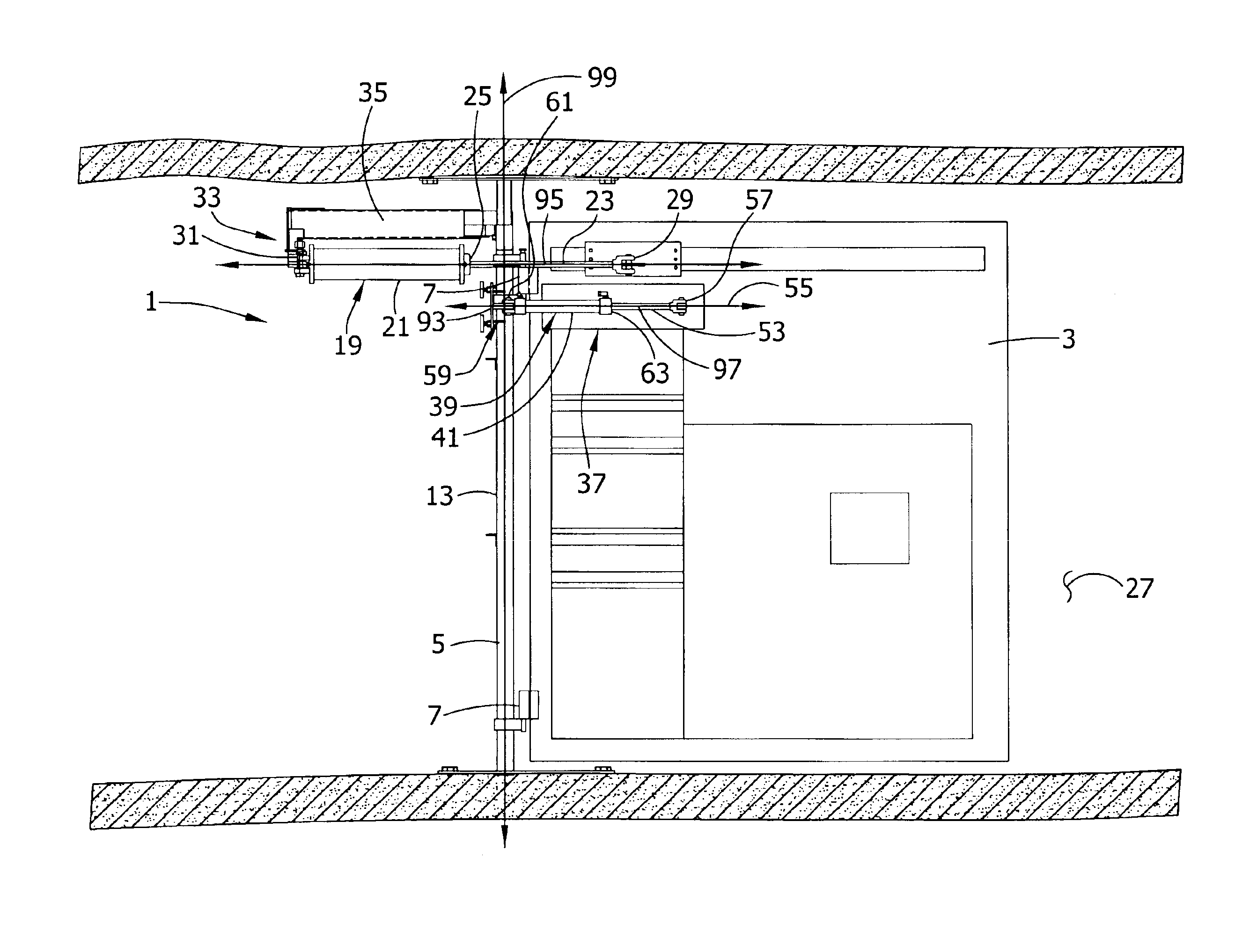
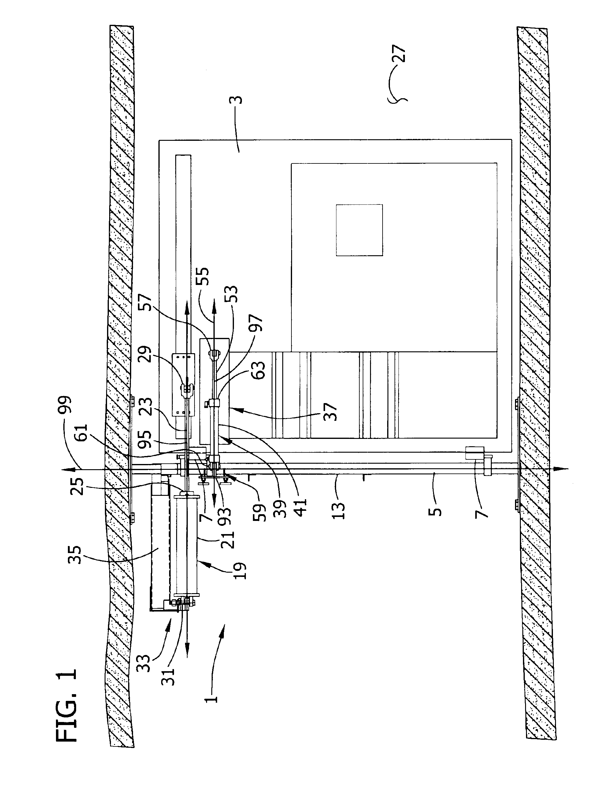
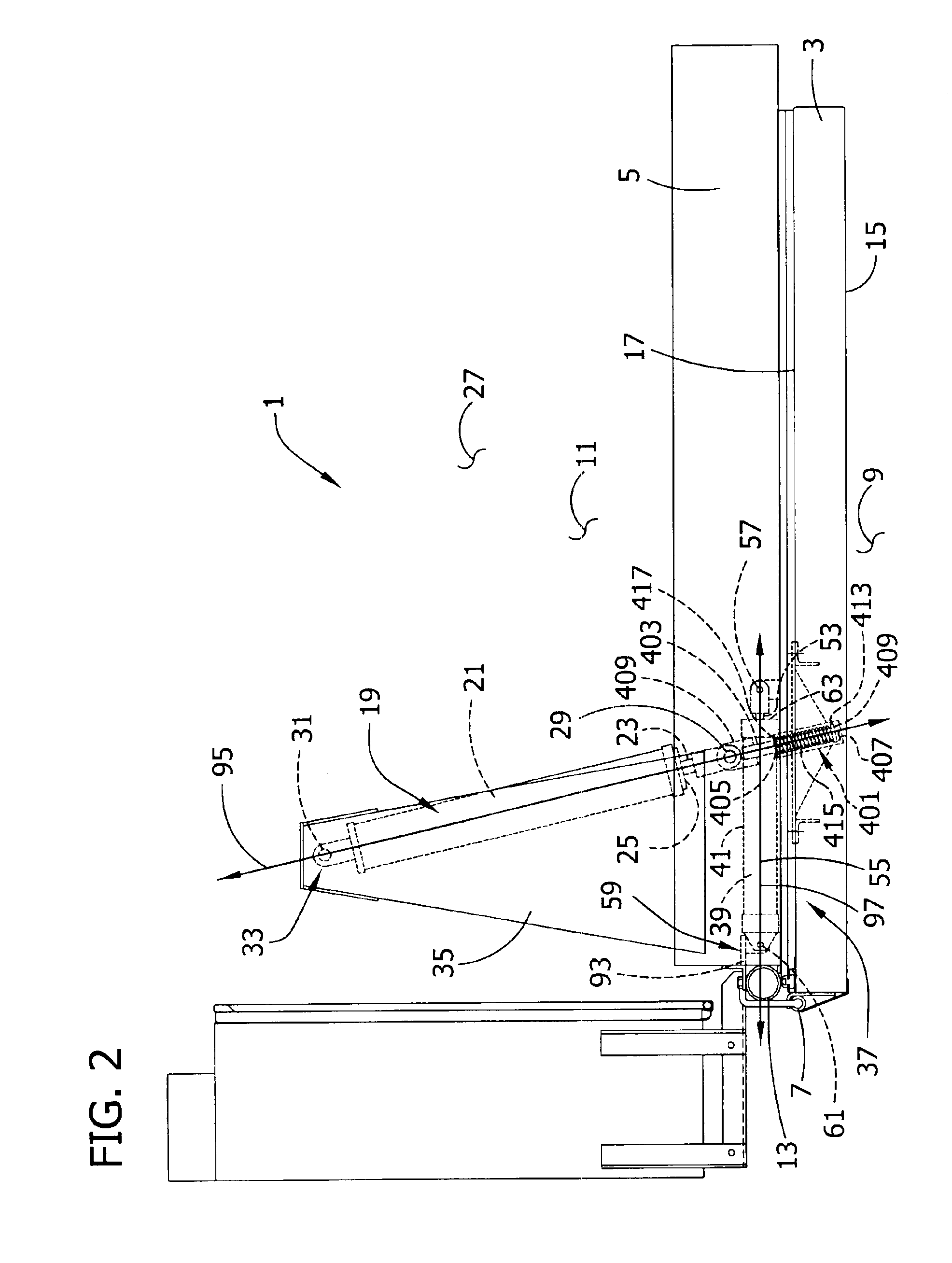
[0030]An exemplary single-leaf door installation of the present invention, generally designated 1, is shown in FIGS. 1-3. The door installation comprises a door frame 5 installed in a mine passageway 27. A door leaf 3 is mounted on a column 13 of the door frame 5, by one or more hinges 7 for example, for back and forth swinging movement of the door leaf 3 between a closed position (FIG. 2) and an open position (FIG. 3). Details on mine door...


PUM


Abstract

A mine door assembly has a frame. At least one door leaf is mounted on the frame for swinging movement between open and closed positions. Movement of the door leaf is powered by a pneumatic actuator. The door installation also has a hydraulic checking system for controlling the speed of the door leaf as it moves back and forth between open and closed positions. A pneumatically-powered control system may be provided to control the door installation. The pneumatic control system may comprise a calibrated vent to shorten the delay in the response of the door leaf to direction from the control system to stop moving. The pneumatic control system may also comprise a limit valve to prevent the door installation from opening when a second door installation is open, thereby preventing both door installations in an air lock from being open at the same time.

Description

FIELD OF INVENTION[0001]The present invention relates to a mine door assembly and more particularly to a pneumatically-powered mine door assembly having a hydraulic checking system.BACKGROUND[0002]Doors used in mines operate under conditions not usually encountered by typical doors. Mine doors have door leafs that tend to be heavy and dimensionally large and are thus subject to large forces due at least in part to ventilation air flow in the mine and consequent air pressure differentials on opposite sides of a door. A leaf can be as large as 10 feet wide and 20 feet high and sometimes even larger. It can weigh more than a thousand pounds when designed for pressure differentials of seven inches of water gauge and over two thousand pounds for a pressure differential of 20 inches of water gauge. Even small pressure differentials can create large forces on the leafs because of their relatively large surface areas. It is difficult to control door leaf movement because of these forces and...

Claims


Application Information

Patent Timeline
Patent Type & Authority Patents(United States)
IPC IPC(8): E05F15/04E05F15/00F15B11/00F15B11/076E05F5/00E05F5/12
CPCE05F15/53F15B11/076E05F5/12E05Y2201/256E05Y2201/264E05Y2900/116E05Y2900/132F15B2211/2053F15B2211/212F15B2211/216F15B2211/30505F15B2211/30525F15B2211/3111F15B2211/31588F15B2211/324F15B2211/40507F15B2211/40515F15B2211/40584F15B2211/41536F15B2211/45F15B2211/455F15B2211/46F15B2211/473F15B2211/50518F15B2211/50554F15B2211/55F15B2211/615F15B2211/6355F15B2211/7128F15B2211/75Y10T16/281Y10T16/27Y10T16/53613E05Y2201/21E05Y2900/40
Inventor KENNEDY, WILLIAM R.KENNEDY, JOHN M.
Owner JACK KENNEDY METAL PRODS & BUILDINGS
Why Eureka
Try Eureka