This helps you quickly interpret patents by identifying the three key elements:
Problems solved by technology
Method used
Benefits of technology
Benefits of technology
[0005]Due to the fact that the turbocharger drives the compressor using engine exhaust gas energy, a delay referred to as a turbo lag is produced in the supercharging response during engine acceleration. The electric supercharger drives the compressor using electrical energy, so the respon
Problems solved by technology
The electric supercharger drives the compressor using electrical energy, so the response is faster than that of the turbocharger, but it cannot be avoided that a certain amount of lag arises due to rotational inertia resistance of rotation components with respect to the timing they start rotation and the timing the rotation speed reaches the required speed for supercharging.
However, if the opening and closing of the bypass valve is simply interlocked with the operation of the electric supercharger as in JP2000-230427A, as the bypass valve closes simultaneously with startup of the electric supercharger, there is the problem that the intake air amount decreases temporarily due to the resistance to intake air presented by the electric supercharger immediately after startup, i.e., the problem is not resolved.
Such a rapid decrease of intake air amount results in undesirable changes to the engine output torque or the air-fuel ratio of the air-fuel mixture supplied to the engine.
Method used
Image
Click on the blue label to locate the original text in one second.
Reading with bidirectional positioning of images and text.
Examples
second embodiment
[0069]Next, referring to FIGS. 4 and 5, this invention will be described.
[0070]First, referring to FIG. 4, in this embodiment, a second air flowmeter 40 which detects a bypass flowrate Qb is installed upstream of the bypass valve 3 of the bypass passage 7.
[0071]Also, the air temperature sensor 32 and the rotation speed sensor 11 of the compressor 2a provided in the first embodiment are omitted in this embodiment. The other features of the hardware of the supercharging device are identical to those of the first embodiment.
first embodiment
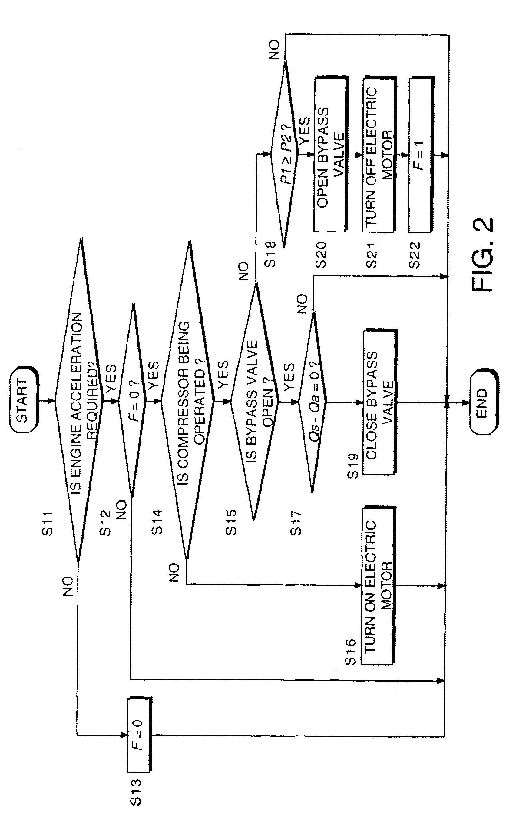
[0072]In the first embodiment, when the flowrate Qs of the compressor 2a is calculated using equation (1) from the rotation speed Nc of the compressor 2a, the pressure P1 of the intake passage 20 and the intake air temperature Ta in the step S17 of FIG. 2, and the flowrate Qs becomes equal to the intake air flowrate Qa detected by the air flowmeter 5, in a step S19, the bypass valve 3 is closed.
[0073]On the other hand, in this embodiment, the initial supercharging control routine shown in FIG. 5 is performed instead of the initial supercharging control routine of FIG. 2.
[0074]In the routine of FIG. 5, a step S17A is provided instead of the step S17 of FIG. 2.
[0075]In the step S17A, the controller 4 determines whether or not the bypass flowrate Qb is zero. When the bypass flowrate Qb is zero, in a step S19, the controller 4 closes the bypass valve 3. When the bypass flowrate Qb is not zero, the processing of steps S18-S22 is performed. The processing other than that of the step S17A ...
third embodiment
[0085]Next, referring to FIG. 6, this invention will be described.
[0086]The supercharging device according to this embodiment is provided with an intercooler 45 between a branch point with the bypass passage 7 of the intake passage 20, and the compressor 1a of the turbocharger 1. The remaining features of the construction are identical to those of the supercharging device according to the first or second embodiments. Due to the intercooler 45, air compressed by the compressor 1a which is at a high temperature, is cooled. As a result, as the heat amount transmitted to the electric motor 2b via the shaft 2c from the compressor 2a becomes small, the operating efficiency of the electric motor 2b improves, and the acceleration performance of the supercharging device improves. Also, as the temperature rise of the electric motor 2b is controlled, if the boost pressure of the turbocharger 1 does not rise for example when climbing a mountain road, supercharging by the compressor 2a can be pe...
PUM
Abstract
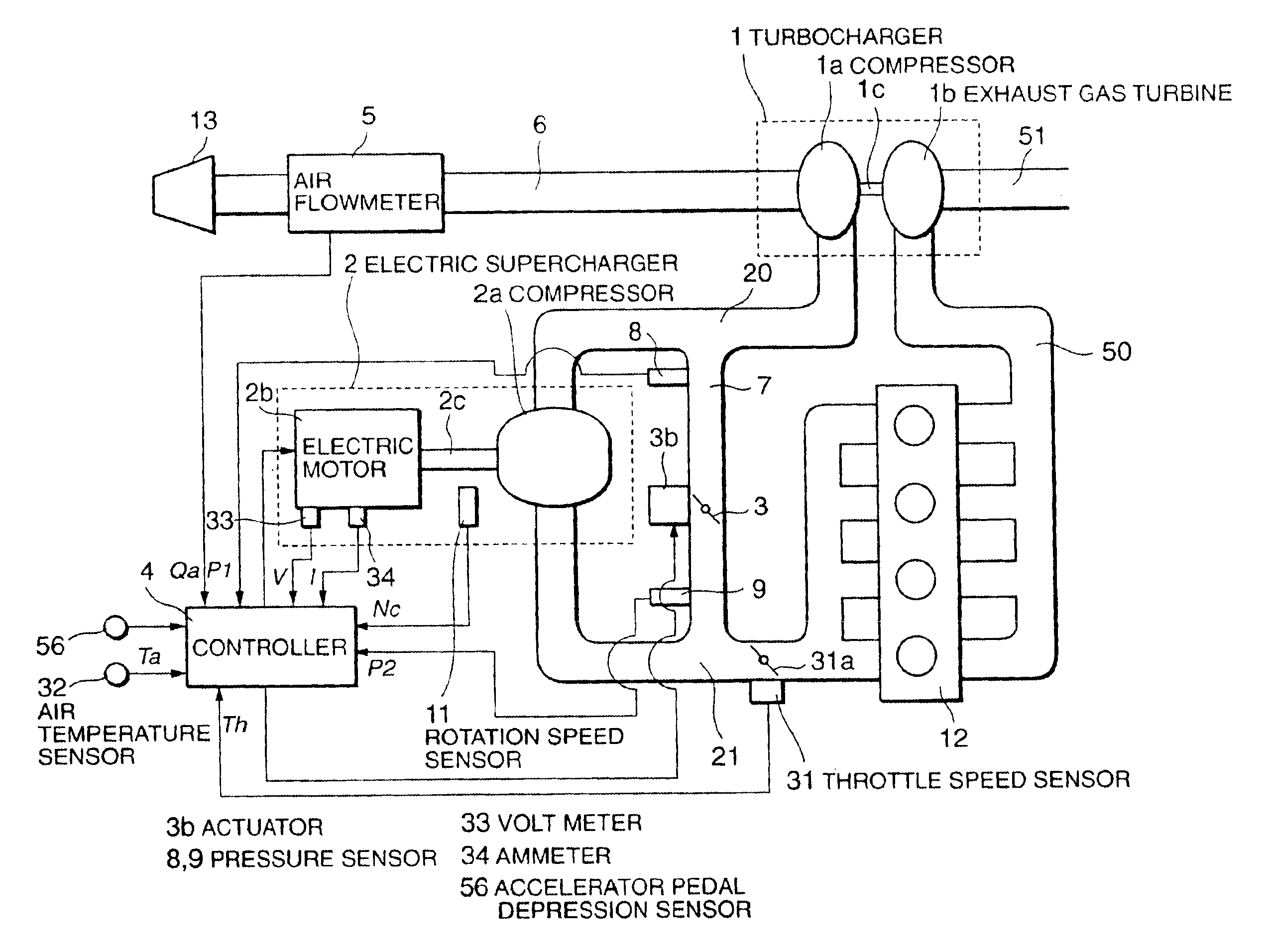
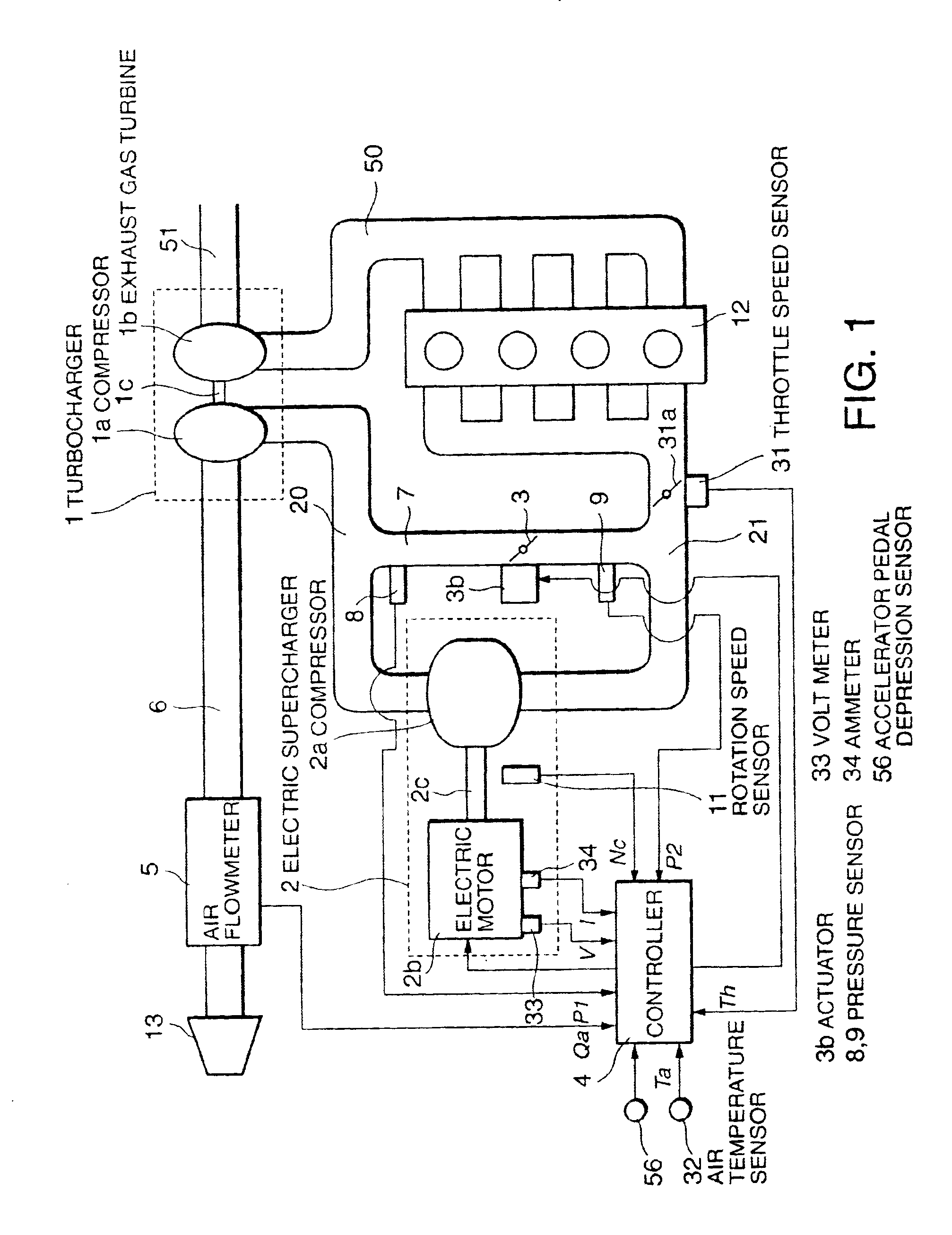
A first compressor (1a) which supercharges intake air is provided in the intake passage (6, 20, 21) of an internal combustion engine (12). The first compressor (1a) is driven by the exhaust gas energy of the engine (12). A second compressor (2a) driven by an electric motor (2b), and a bypass valve (3) which bypasses the second compressor (2a), are provided in the intake passage (7, 20, 21) between the first compressor (1a) and the engine (12). The bypass valve (3) shifts from the open state to the closed state according to the operation of the second compressor (2a). At this time, the bypass valve (3) starts closing at some time after startup of the second compressor (2a) so that the intake air amount of the engine (12) is not deficient.
Description
FIELD OF THE INVENTION[0001]This invention relates to the supercharging of an internal combustion engine.BACKGROUND OF THE INVENTION[0002]JP2002-021573A published by the Japanese Patent Office in 2002 discloses a turbocharger and an electric supercharger used together for an internal combustion engine for vehicles, in order to obtain a desirable supercharging performance.[0003]The electric supercharger comprised a compressor driven by an electric motor, this compressor and the compressor of the turbocharger being arranged in series in an engine intake passage.[0004]JP2000-230427A published by the Japanese Patent Office in 2000 discloses an electric supercharger in the intake passage of an internal combustion engine, and a bypass valve which bypasses the electric supercharger. The bypass valve is closed when the electric supercharger is operated, i.e., during supercharging, and is opened when the electric supercharger is not operated, i.e., during natural aspiration.SUMMARY OF THE IN...
Claims
Application Information
Patent Timeline
Application Date:The date an application was filed.
Publication Date:The date a patent or application was officially published.
First Publication Date:The earliest publication date of a patent with the same application number.
Issue Date:Publication date of the patent grant document.
PCT Entry Date:The Entry date of PCT National Phase.
Estimated Expiry Date:The statutory expiry date of a patent right according to the Patent Law, and it is the longest term of protection that the patent right can achieve without the termination of the patent right due to other reasons(Term extension factor has been taken into account ).
Invalid Date:Actual expiry date is based on effective date or publication date of legal transaction data of invalid patent.

