Disposable plug for warming the inner ear

Active Publication Date: 2005-09-06
GREENHAW SAREVA L +1
View PDF27 Cites 17 Cited by
  • Summary
  • Abstract
  • Description
  • Claims
  • Application Information

AI Technical Summary

Benefits of technology

[0005]In accordance with the invention, a disposable plug is provided for generating heat to warm an ear canal. A mask has a leading surface contoured for insertion into the outer ear for abutment against a wall of the outer ear surrounding the entrance to the ear canal. An orifice through the wall of the mask aligns with and at the entry into the ear canal when the plug is inserted into the outer ear and abuts the wall at the entrance. A sealed envelope has a leading tip that extends forward of the orifice and a trailing reservoir that extends rearward of the orifice and the trailing surface of the mask. The leading tip of the envelope is elastic and contoured to extend into the ear canal when the mask abuts the wall at the entrance to the ear canal. The trailing reservoir has a forward wall, a main body and a rear wall. The forward wall of the reservoir is contoured to comply against the trailing surface of the mask. A super-cooled liquid salt substantially fills the envelope. The envelope is sized to contain a sufficient quantity of the liquid salt to deliver heat to the inner ear at a predetermined temperature for a predetermined time period. A disk which is convex in relation to the mask is disposed in the reservoir and immersed in the liquid salt. The rear wall of the reservoir is connected to the disk. The periphery of the body of the reservoir taken along a generally vertical plane is clamped between the periphery of the mask and the periphery of the disk. As a result of this peripheral clamping, when the mask abuts the wall of the outer ear and the disk is pressed toward the mask, the disk will pop from c

Problems solved by technology

All of these devices suffer from one or more common deficiencies.
They are structurally complex and, therefore, unwieldy for the care-giver and uncomfortable for the patient.
They have many rigid components that inhibit adaptability to the unique anatomical structure of individual patients.
Their time and temperature controls are so complex as to appreciably increase both

Method used


Image

  • Disposable plug for warming the inner ear
  • Disposable plug for warming the inner ear
  • Disposable plug for warming the inner ear

Examples


Example

[0016]While the invention will be described in connection with preferred embodiments thereof, it will be understood that it is not intended to limit the invention to those embodiments or to the details of the construction or arrangement of parts illustrated in the accompanying drawings.

DETAILED DESCRIPTION

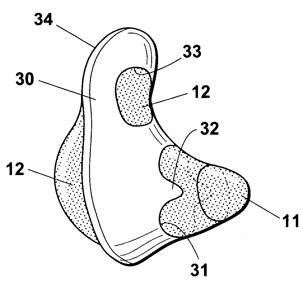
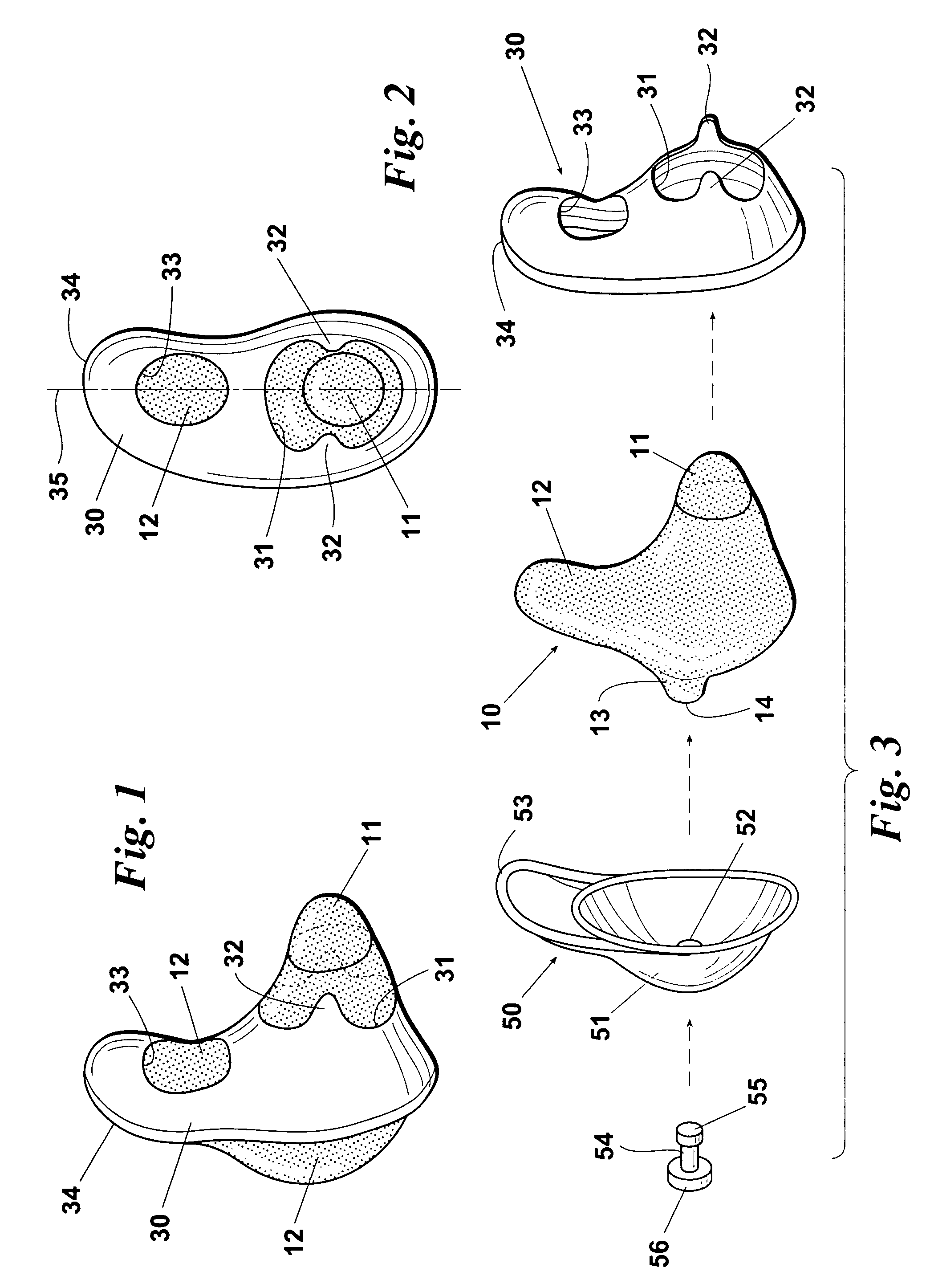
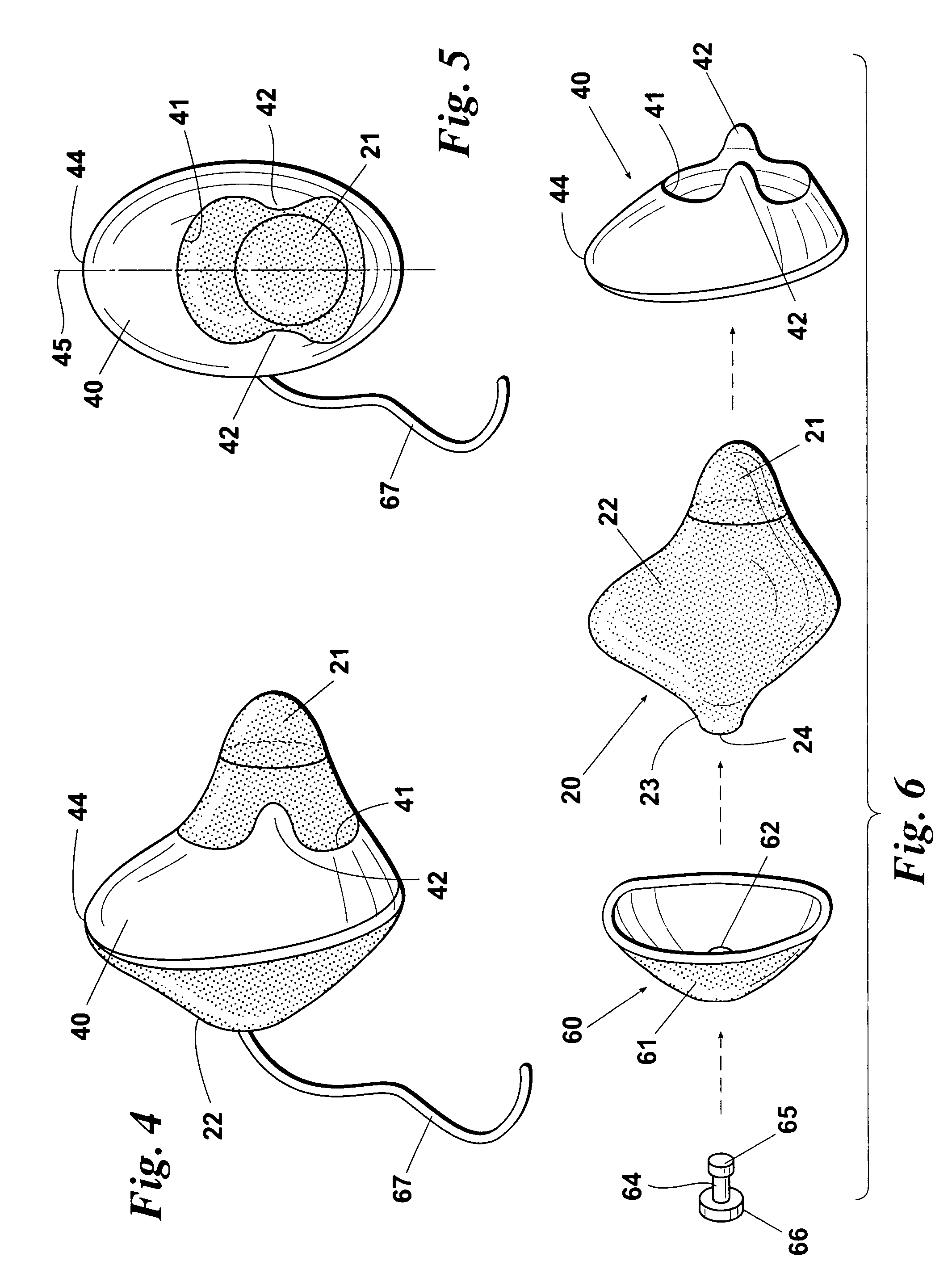
[0017]Looking at the FIGS. 1–3, an asymmetrical embodiment of a disposable plug for generating heat to warm an ear canal is illustrated. As best seen in FIG. 3, the principle structural components of the asymmetrical plug are an envelope 10, a mask 30 and a trigger 50.

The Envelope

[0018]The primary functions of the envelope 10 or 20 are to contain the phase-change heat-generating chemicals of the plug and to penetrate into and conform to the ear canal C in the initial stages of activation. The envelope 10 or 20 has two major portions, a leading tip 11 or 21 and a trailing reservoir 12 or 22. In the pre-activated state of the plug the entire envelope 10 or 20, including the tip 11 or...


PUM


Abstract

A disposable plug has a mask with an orifice aligned at the entry into the ear canal when the plug is inserted into the ear. A sealed envelope has a leading elastic tip that extends forward of the orifice into the ear canal and a trailing reservoir that extends rearward of the orifice. A super-cooled liquid salt substantially fills the envelope. The envelope is sized to contain a sufficient quantity of the liquid salt to deliver heat to the inner ear at a predetermined temperature for a predetermined time period. A convex disk in the reservoir can be manually popped to concave after the tip of the envelope has been inserted into the ear canal to shrink the reservoir and expand the tip into deeper extension into and compliance with the ear canal and to activate solidification of the liquid salt to generate heat into the ear canal.

Description

BACKGROUND OF THE INVENTION[0001]This invention relates generally to devices for therapeutic treatment of the human ear and more particularly concerns a disposable plug for warming the inner ear.[0002]Warming the ear is an accepted method of relieving inner ear pain. Inner ear relief is commonly accomplished, though to a limited extent, by warming the outer ear to achieve a resultant heat transfer to the inner ear. Known outer ear warming devices generally have an insulated housing that covers the outer ear. A hollow chamber within the housing stores a heat source, typically a heated liquid such as hot water or a phase-change salt or oil such as a carboxymethylcellulose mixture. In some of these devices, the heat source is introduced into its chamber for each use. For example, boiling water is poured into the chamber and, after use, the cooled water is drained from the chamber. In others, a permanent heat source is provided in the chamber and the device is placed in a microwave oven...

Claims


Application Information

Patent Timeline
IPC IPC(8): A61F11/08A61F11/00
CPCA61F11/08
Inventor GREENHAW, SAREVA L.DIONIGI, LAMBERTO
Owner GREENHAW SAREVA L
Why Eureka
Try Eureka