Nail lockout assembly

a technology of nail lockout and assembly, which is applied in the direction of nailing tools, manufacturing tools, stapling tools, etc., to achieve the effect of significantly reducing the risk of tool damag

Inactive Publication Date: 2005-09-06
BLACK & DECKER INC
View PDF38 Cites 39 Cited by
  • Summary
  • Abstract
  • Description
  • Claims
  • Application Information

AI Technical Summary

Benefits of technology

[0006]Accordingly, the present invention is directed to a nail lockout assembly disposed within a pneumatic tool, such as a nail gun, which provides an operator of the pneumatic tool an effective way to ensure that only the correct instruments are loaded and advanced within the tool. The tool itself becomes a regulating device, in effect identifying for the operator whether the nails the operator has chosen are correct for the particular tool. By using the present invention, risk of harm to the tool may be significantly diminished, even if the operator is relatively inexperienced simply because the nails may not be allowed to advance in the tool if they are incorrect. In a first aspect of the present invention, a nail lockout assembly includes a slotted guide member for engaging a projection disposed in a nail loading assembly and for identifying to the nail lockout assembly the angle of coupling of a nail loading assembly to a nail driving assembly. The slotted guide member is coupled to a

Problems solved by technology

If the nails are incorrectly positioned then they are not allowed t

Method used


Image

  • Nail lockout assembly
  • Nail lockout assembly
  • Nail lockout assembly

Examples


Embodiment Construction

[0019]Reference may now be made in detail to the presently preferred embodiments of the invention, examples of which are illustrated in the accompanying drawings.

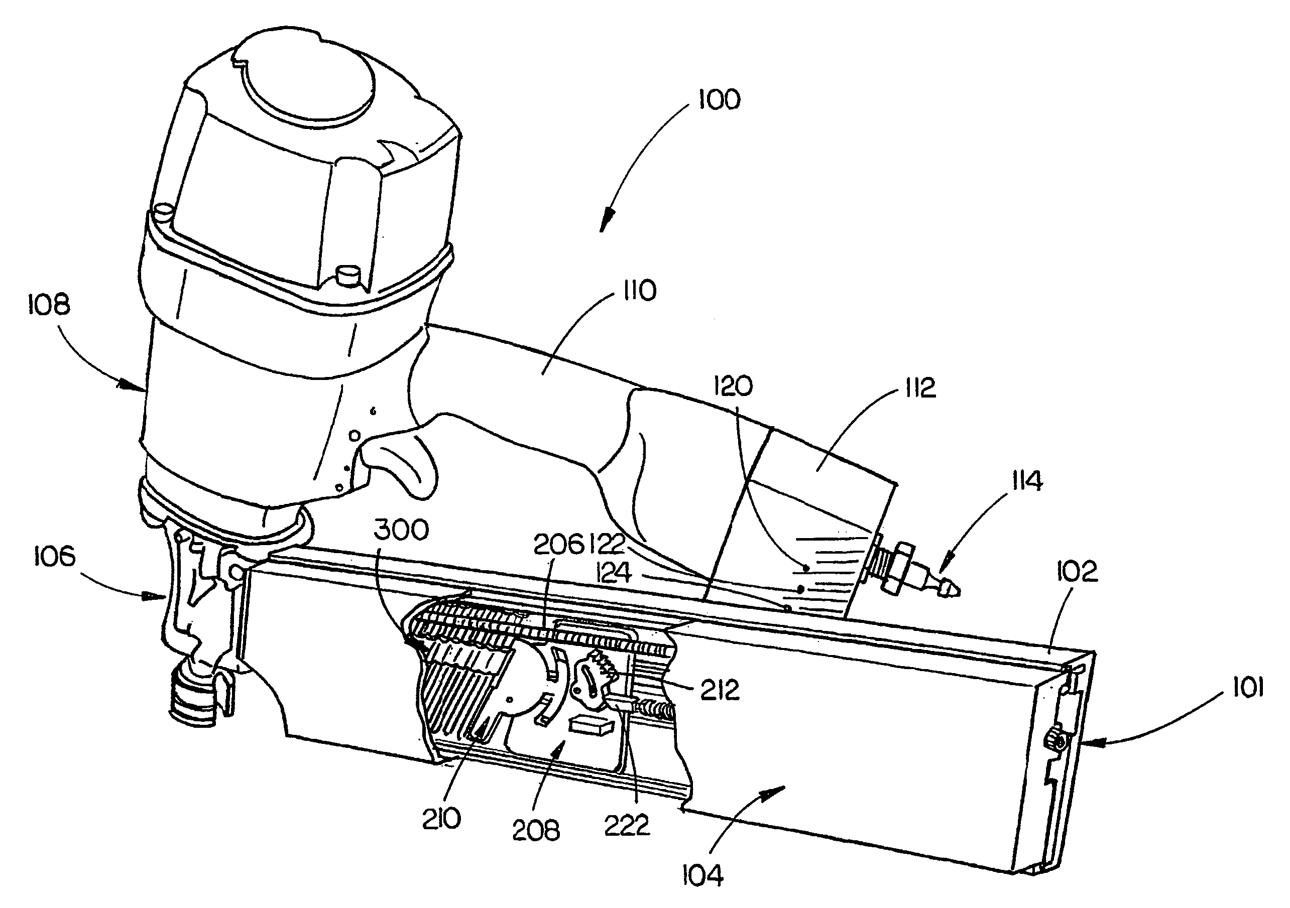
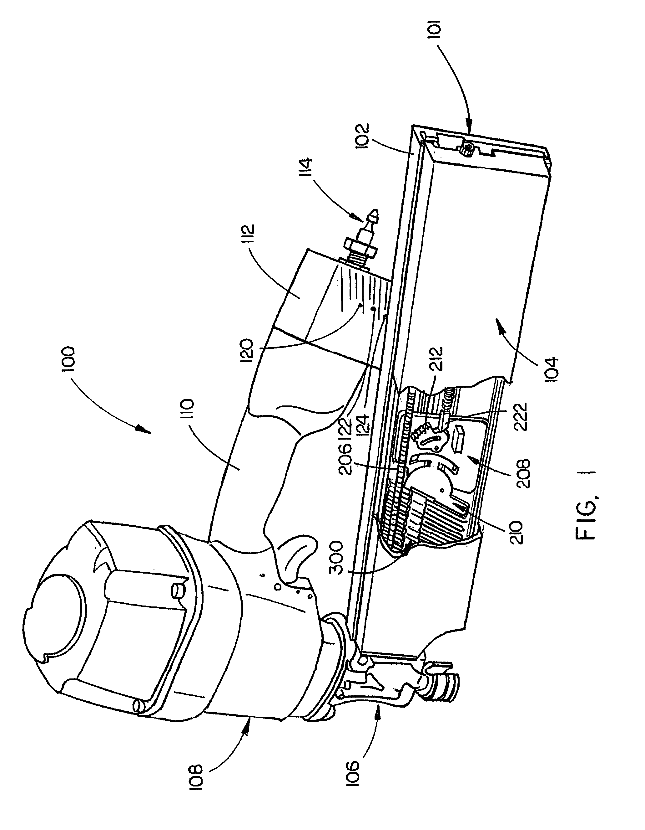
[0020]Referring generally now to FIGS. 1 through 6, exemplary embodiments of the present invention are shown. In FIG. 1 an adjustable angle nail gun assembly including an adjustable angle magazine 101 is shown. It is understood that while the preferred embodiments exemplify an adjustable angle magazine 101, other nail gun magazine or nail loading assembly configurations may be employed without departing from the scope and spirit of the present invention. The adjustable angle magazine 101 includes a housing 102 and a cover 104 and is shown enabled to couple with an adjustable angle nose casting assembly 106. The adjustable angle nail gun further comprises a casing 108 disposed with a nail driving assembly, the casing 108 is coupled with the adjustable angle nose casting assembly 106. A handle 110 couples with the casing 108 ...


PUM

PropertyMeasurementUnit
Angleaaaaaaaaaa

Abstract

A nail lockout assembly provides a way for an operator of a nail gun to have determined whether the nails being employed are properly aligned to allow for efficient operation of the nail gun. The nail lockout assembly may be employed in a nail loading assembly, such as an adjustable angle magazine, which is coupled with a nail driving assembly. A slotted guide member disposed in a housing of the nail loading assembly provides a determination of the angle of the nail loading assembly relative to the nail driving assembly through operational engagement with a projection. A linkage bar is coupled with the slotted guide member and translates the angle of the nail loading assembly to a pusher which engages a nail loaded in the nail loading assembly. A cover serrated member is coupled with a cover of the nail loading assembly. A pawl assembly is coupled with the linkage bar and may engage with the cover serrated member. An adapter couples with the pusher and the pawl assembly enabling rotational movement in each. The nail improperly aligned with the pusher causes the pawl assembly to engage with the cover serrated member and prevents the cover from closing along with preventing the pusher from advancing the nail in the nail loading assembly.

Description

CROSS REFERENCE TO RELATED APPLICATION[0001]The present application claims priority under 35 U.S.C. §119(e) to the U.S. Provisional Application Ser. No. 60 / 411,563, filed on Sep. 18, 2002, and the U.S. Provisional Application Ser. No. 60 / 471,641, filed on May 19, 2003. The U.S. Provisional Application 60 / 411,563 and 60 / 471,641 are herein incorporated by reference in their entireties.FIELD OF THE INVENTION[0002]The present invention generally relates to the field of power tools, and particularly to a nail lockout assembly for use in a nail gun, such as a pneumatic nail gun.BACKGROUND OF THE INVENTION[0003]The use of power tools is commonplace in many workplace environments. A nail gun, such as pneumatic nail gun require the use of instruments (i.e., nails) that meet specific conditions in order to ensure proper operation of the nail gun. Use of incorrect nails may result in damage to the tool and lost time and money. Unfortunately, the tool itself often does not provide any effective...

Claims


Application Information

Patent Timeline
IPC IPC(8): B25C1/00
CPCB25C1/005B25C1/008
Inventor SCHNELL, JOHN W.
Owner BLACK & DECKER INC
Why Eureka
Try Eureka